Learning Advanced Features
191
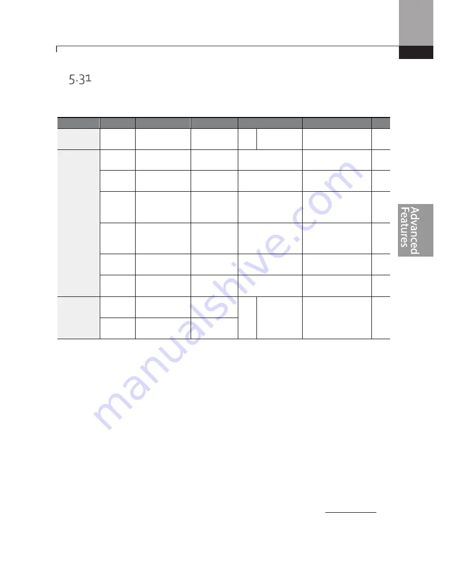
Brake Control
Brake control is used to control the On/Off operation of electronic brake load system.
A multi-
function output (Relay1 or Q1) is used to engage and disengage the load brake (self locking
electromechanical device) that holds the load in place.
Group
Code
Name
LCD Display
Parameter Setting Setting Range
Unit
dr
09
Control mode
Control
Mode
0
V/F
-
-
Ad
41
Brake open
current
BR Rls Curr
50.0
0.0–180%
%
42
Brake open
delay time
BR Rls Dly
1.00
0.0–10.0
sec
44
Brake open
forward
frequency
BR Rls Fwd
Fr
1.00
0
–
Maximum
frequency
Hz
45
Brake open
reverse
frequency
BR Rls Rev Fr 1.00
0
–
Maximum
frequency
Hz
46
Brake close
delay time
BR Eng Dly
1.00
0.00–10.00
sec
47
Brake close
frequency
BR Eng Fr
2.00
0
–
Maximum
frequency
Hz
OU
31
Multi-function
relay1 item
Relay 1
35
BR Control
:
-
-
33
Multi-function
output1 item
Q1 Define
When either of the multi-funcion outputs are set to BR Control, the DC injection braking functions
at start (Ad.07) and the dwell functions (Ad.20) do not operate.
•
Brake release sequence:
During motor stop state, when a run command is applied, the
inverter accelerates up to brake release frequency (Ad.44
–
45) in forward or in reverse
direction. After reaching brake release frequency, if motor current reaches brake release
current (BR Rls Curr), the multi-function output (Relay1 or Q1) sends a release signal (closes) to
release the mechanical brake. Once the signal has been sent, acceleration will begin after
maintaining frequency for brake release delay time (BR Rls Dly).
•
Brake engage sequence:
When
a stop command is sent during operation, the motor
decelerates. Once the output frequency reaches the brake engage frequency (BR Eng Fr), the
motor stops deceleration and the multi-function output (Relay1 or Q1) sends out a brake
engage signal (opens) to engage the mechanical brake. Frequency is maintained for the brake
engage delay time (BR Eng Dly) and will become 0ff afterwards. If DC injection braking time
(Ad.15) and DC injection braking rate (Ad.16) are set (Stop Mode settings), inverter output is
blocked after DC injection braking. For DC injection braking, refer to 4.17.2
Stop with DC B
.
Содержание Rsi S Series
Страница 2: ......
Страница 6: ......
Страница 12: ...Preparing the Installation 0...
Страница 22: ...Preparing the Installation 10...
Страница 70: ...LearningAdvanced Features 58...
Страница 152: ...LearningAdvanced Features 140 PID controlblock diagram...
Страница 224: ...LearningAdvanced Features 212...
Страница 356: ...344...
Страница 362: ...Maintenance 350...
Страница 381: ...369 TechnicalSpecification...
Страница 397: ......


