


IDT Usage Models
PES32NT24xG2 User Manual
26 - 32
January 30, 2013
Notes
For example, RC2 uses NT multicast overlay register set 0, programs the overlay address to base
0x0510_0000, and programs the overlay requester ID to match that of the NT function in port 8. Also, RC3
uses NT multicast overlay register set 0, programs the overlay address to base 0x0820_0000, and
programs the overlay requester ID to match that of the NT function in port 16.
RC0, in preparation for the multicast operation, programs the PCI Express multicast capability structure
in the NT endpoint of port 0. This structure is programmed to support a multicast aperture of 1 MB with 4
multicast groups (i.e., groups 0 to 3, the maximum number of groups supported for NT multicast). The multi-
cast window starts at base address 0x0110_0000.
In addition, RC0 programs the NT Multicast Group x Port Association (NTMCG[3:0]PA) register to indi-
cate that multicast groups 0 to 3 are all associated with ports 4, 8, and 16. In this way, a posted address-
routed TLP received by the NT function in port 0 that falls within any of multicast groups 0 to 3 is NT multi-
casted to ports 4, 8, and 16.
NTMCG[3:0]PA.PORTVEC = 0x010088 (i.e., bits corresponding to ports 4, 8, and 16 are set).
At this point, the NT multicast mechanism is ready. To perform an NT multicast transfer, RC0 need only
issue a posted address-routed TLP (e.g., memory write TLP) that falls within the multicast window associ-
ated with the NT function in port 0 (i.e., from address 0x0110_0000 to 0x011F_FFFF).
In this example, RC0 wishes to use the DMA in the switch’s port 0 to transfer data from host memory to
the memory associated with RC1, RC2, and RC3. To do this, RC0 sets up the DMA descriptors in its
memory. The data transfer descriptors are programmed such that the source address points to the location
in RC0’s memory where the data to be transferred is located, while the destination address points to a loca-
tion within the multicast window associated with the NT function in port 0.
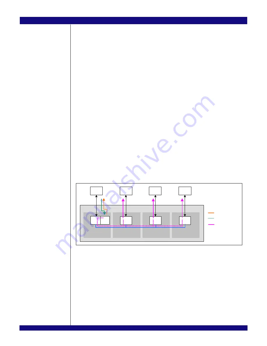
When the DMA starts transferring the data, it will read the data from RC0’s memory, convert the
received completion TLPs to memory write TLPs, and transfer these to the destination address
programmed in the descriptor. Since the destination address falls within the NT function’s multicast window
in partition 0, the switch will NT multicast the data to the programmed ports (i.e., ports 4, 8, and 16). Figure
26.20 shows the transfer.
Figure 26.20 PES32NT24xG2 with Port 0 Configured in NT Function with DMA Mode
and Ports 4, 8, and 16 in NT Function Mode
When the TLPs emerge on ports 4, 8, and 16, they will have the requester ID and address programmed
in the NT multicast egress processing registers of each of these ports. For example, NT multicast TLPs
emitted by port 4 will have:
–
Requester ID = <Requester ID of the NT function in port 4> (i.e., as programmed in the
OVRREQID field in port 4’s NTMCOVR0C register).
–
Address = { 0x0AA, DMA Destination Address[19:0] }
When the DMA finishes the transfer, it notifies RC0 via an interrupt. In order to notify RC1, RC2, and
RC3, DMA immediate descriptors may be used in conjunction with the NT doorbell mechanism. Refer to
section Immediate Descriptor Usage on page 26-20 for an example of this.
RC1
Partition 1
P 4
( NT)
RC2
Partition 2
P 8
(NT)
RC3
Partition 3
P 16
(NT)
RC0
Partition 0
NT
Switch
DMA
NT Interconnect
Cpl
Mem
Write
Mem
Write
Mem
Write
DMA Request
Completions with Data
Memory Write TLPs
( NT Multicasted)
Port 0
Req
Summary of Contents for PCI Express 89HPES32NT24xG2
Page 20: ...IDT Table of Contents PES32NT24xG2 User Manual x January 30 2013 Notes...
Page 24: ...IDT List of Tables PES32NT24xG2 User Manual xiv January 30 2013 Notes...
Page 28: ...IDT List of Figures PES32NT24xG2 User Manual xviii January 30 2013 Notes...
Page 56: ...IDT PES32NT24xG2 Device Overview PES32NT24xG2 User Manual 1 20 January 30 2013 Notes...
Page 100: ...IDT Switch Core PES32NT24xG2 User Manual 4 22 January 30 2013 Notes...
Page 128: ...IDT Failover PES32NT24xG2 User Manual 6 4 January 30 2013 Notes...
Page 148: ...IDT Link Operation PES32NT24xG2 User Manual 7 20 January 30 2013 Notes...
Page 164: ...IDT SerDes PES32NT24xG2 User Manual 8 16 January 30 2013 Notes...
Page 170: ...IDT Power Management PES32NT24xG2 User Manual 9 6 January 30 2013 Notes...
Page 196: ...IDT Transparent Switch Operation PES32NT24xG2 User Manual 10 26 January 30 2013 Notes...
Page 244: ...IDT SMBus Interfaces PES32NT24xG2 User Manual 12 40 January 30 2013 Notes...
Page 247: ...IDT General Purpose I O PES32NT24xG2 User Manual 13 3 January 30 2013 Notes...
Page 248: ...IDT General Purpose I O PES32NT24xG2 User Manual 13 4 January 30 2013 Notes...
Page 330: ...IDT Switch Events PES32NT24xG2 User Manual 16 6 January 30 2013 Notes...
Page 342: ...IDT Multicast PES32NT24xG2 User Manual 17 12 January 30 2013 Notes...
Page 344: ...IDT Temperature Sensor PES32NT24xG2 User Manual 18 2 January 30 2013 Notes...
Page 384: ...IDT Register Organization PES32NT24xG2 User Manual 19 40 January 30 2013...
Page 492: ...IDT Proprietary Port Specific Registers PES32NT24xG2 User Manual 21 44 January 30 2013 Notes...
Page 588: ...IDT NT Endpoint Registers PES32NT24xG2 User Manual 22 96 January 30 2013 Notes...
Page 710: ...IDT JTAG Boundary Scan PES32NT24xG2 User Manual 25 12 January 30 2013 Notes...
Page 743: ...IDT Usage Models PES32NT24xG2 User Manual 26 33 January 30 2013 Notes...
Page 744: ...IDT Usage Models PES32NT24xG2 User Manual 26 34 January 30 2013 Notes...