User Manual
23
Rev. 1.1
2019-03-18
TLE984xQX
Microcontroller with LIN and Power Switches for Automotive Applications
Modes of Operation
4
Modes of Operation
This highly integrated circuit contains analog and digital functional blocks. For system and interface control
an embedded 32-Bit Cortex®-M0 microcontroller is included. For internal and external power supply purposes,
on-chip low drop-out regulators are existent. An internal oscillator (no external components necessary)
provides a cost effective and suitable clock in particular for LIN slave nodes. As communication interface, a LIN
transceiver and several High Voltage Monitor Inputs with adjustable threshold and filters are available.
Furthermore one or twoHigh-Sides Switches (e.g. for driving LEDs or powering of switches), two low-side
switches (e.g. for relays) and several general purpose input/outputs (GPIO) with pulse-width modulation
(PWM) capabilities are available.
The Micro Controller Unit supervision and system protection including reset feature is controlled by a
programmable window watchdog. A cyclic wake-up circuit, supply voltage supervision and integrated
temperature sensors are available on-chip.
All relevant modules offer power saving modes in order to support terminal 30 connected automotive
applications. A wake-up from the power saving mode is possible via a LIN bus message, via the monitoring
inputs or repetitive with a programmable time period (cyclic wake-up).
The integrated circuit is available in a package with 0.5 mm pitch and is designed to withstand the challenging
conditions of automotive applications.
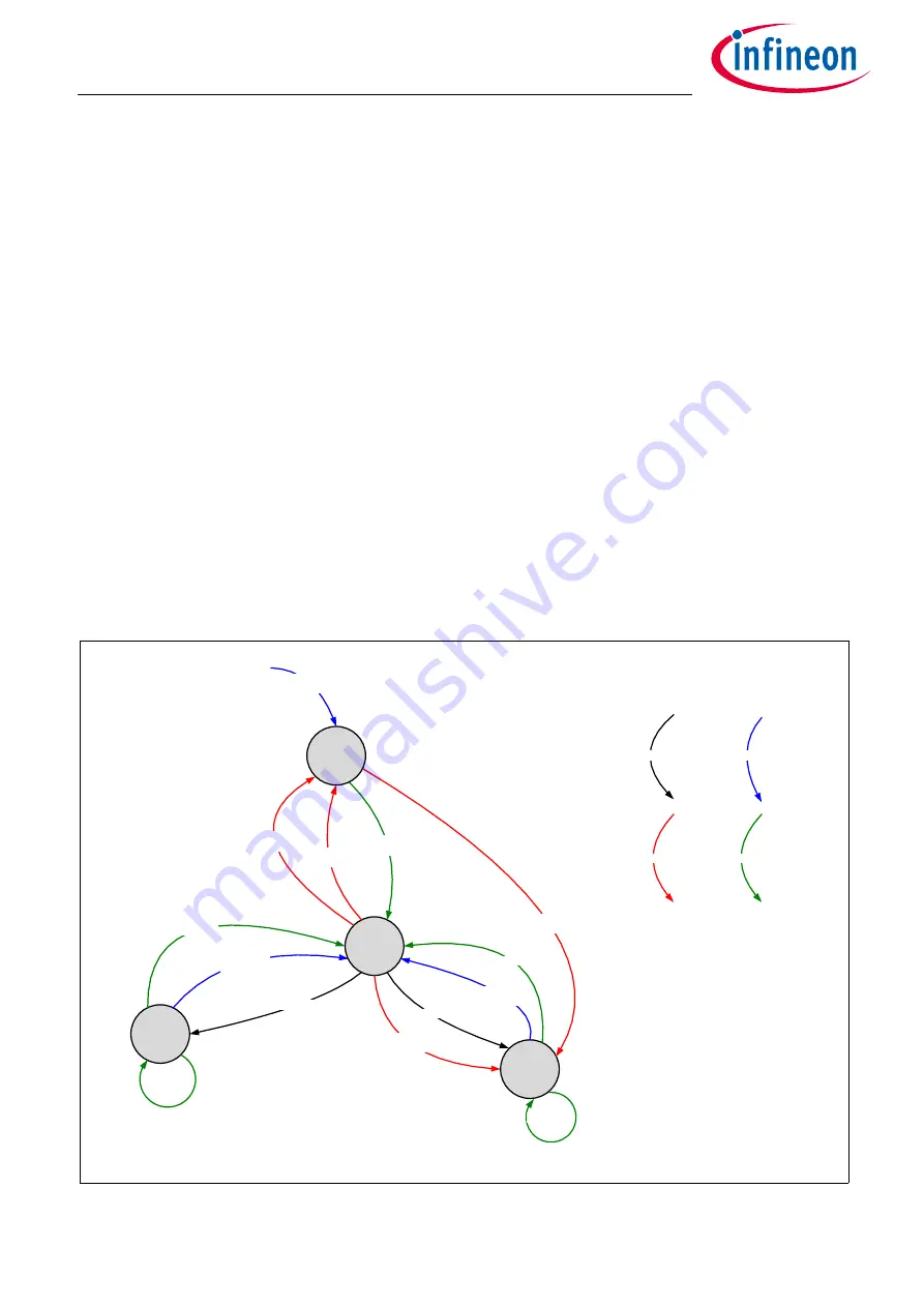
The TLE984xQX has several operational modes mainly to support low power consumption requirements. The
low power modes and state transitions are depicted in
below.
Figure 3
Power Control State Diagram
Safety Fallback
SLEEP command
Sleep Mode
Active Mode
Stop Mode
STOP command
Transition by software
Transition by external event
LIN wake or
MON wake
LIN wake or
MON wake or
GPIO wake
Power-up
VS > 3V
Cyclic-sense
Cyclic wake
Cyclic wake
VDDC stable &
error_supp < 5
VDDC fail
(err+)
WDT1 reset
(er+)
Safety fallback
error_supp = 5
Safety fallback
error_wdt = 5
Transition by internal event
Cyclic-sense
Reset
PMU_System_Modes.vsd


