User Manual
966
Rev. 1.1
2019-03-18
TLE984xQX
Microcontroller with LIN and Power Switches for Automotive Applications
Application Information
28.2
Motor Drive with P/N-channel Power MOSFET Half Bridge Application (only
TLE9845QX)
Note:
The following information is given as a hint for the implementation of the device only and shall not
be regarded as a description or warranty of a certain functionality, condition or quality of the device.
28.2.1
P/N-channel Half Bridge Application diagram
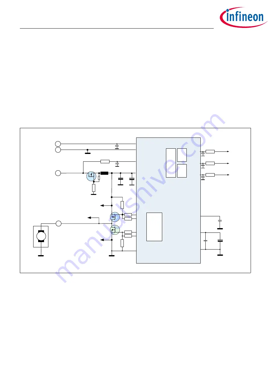
Figure 223 Scheme of relevant blocks used for single phase brushed-DC-motor control
28.2.2
Functional description
28.2.2.1 Gate Driver Stages
shows a simplified diagram with TLE984xQX in an electric drive application setup controlling an
uni-directional brushed-DC-motor. The driver stages support two variants to drive the motor: The non
controlled motor contact can be connected to battery or to ground potential.
The half bridge is built up with a P-channel power MOSFET in high-side and a N-channel power MOSFET in low-
side position. The driver stage of the P- and N-channel MOSFET is provided by the outputs HS1/LS1 and
HS2/LS2, respectively. Each pair of outputs builds up a push-pull gate driver stage with fixed supply to VS and
TLE9845QX
V
BAT
LIN
GND
VBAT_ SENSE
VS
GND
LIN
MON1
LS1
LS2
MON2
MON4
C
MON4
C
MON2
C
MON1
R
MON1
R
MON4
R
MON2
R
VBAT _SENSE
C
2VS
C
1VS
C
VBAT _SENSE
C
LIN
M
M2
M4
GNDLS
M2
M1
Optional
L
VS
R
RPP1
R
PUHS
R
GHS1
R
GHS 2
Q
LS
Q
HS
R
RPP 2
M+
M1
HS2
HS1
M4
VDDC
VDDP
GND
C
VDDC
C
VDDP
C
ZVDDP
R
GLS1
R
GLS2
R
PDLS
Capture
Compare Unit
CCU6
for PWM
generation
DU
diffe-
rential
unit
DU
diffe-
rential
unit
ADC1
P
N


