Chapter 9 SDRAM Controller
9-17
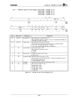
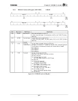
9.4.3
SDRAM Command Register (SDCCMD)
0x802C
31
24
23
16
MDLNO
VERNO
R
R
:
Type
0x21 0x10
: Initial
value
15
8
7 4
3 0
Reserved CCE CMD
R/W
R/W
: Type
0x0
0x0
: Initial
value
Bits Mnemonic Field
Name
Description
31:24
MDLNO
Model Number
Model Number (Initial value: 0x21, R)
Indicates the model number. The default value is 0x30 for the TX4925. This field is
Read Only.
23:16
VERNO
Version Number
Version Number (Initial value: 0x10, R)
Indicates the version number. The default value is 0x10 for the TX4925. This field is
Read Only.
15:8
⎯
Reserved
⎯
7:4 CCE
Command
Channel Enable
Command Channel Enable (Initial value: 0x0, R/W)
Setting one of these bits to “1” enables the command of the corresponding channel.
This command is simultaneously executed on all channels that are enabled.
Bit 7: Channel 3
Bit 6: Channel 2
Bit 5: Channel 1
Bit 4: Channel 0
3:0
CMD
Command
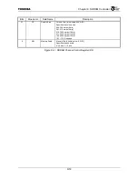
Command (Initial value: 0x0, R/W)
Specifies a command that is performed on memory.
0x0: NOP command
0x1: Set Mode Register command
Set SDRAM Mode Register from SDCTR value
0x2: Reserved
0x3: Precharge All command
Precharge All SDRAM Banks
0x4: Self-Refresh Mode command
Sets SDRAM to the Self-Refresh Mode
0x5: Power Down Mode Command
Set SDRAM to the Power Down Mode
0x6: Normal Mode Command
Cancel Self-Refresh/Power Down Mode
0x7-0xf: Reserved
Figure 9.4.3 SDRAM Command Register
Summary of Contents for TMPR4925
Page 1: ...64 Bit TX System RISC TX49 Family TMPR4925 Rev 3 0 ...
Page 4: ......
Page 15: ...Handling Precautions ...
Page 16: ......
Page 18: ...1 Using Toshiba Semiconductors Safely 1 2 ...
Page 40: ...3 General Safety Precautions and Usage Considerations 3 18 ...
Page 42: ...4 Precautions and Usage Considerations 4 2 ...
Page 43: ...TMPR4925 ...
Page 44: ......
Page 54: ...Chapter 1 Features 1 8 ...
Page 58: ...Chapter 2 Block Diagram 2 4 ...
Page 88: ...Chapter 4 Address Mapping 4 12 ...
Page 226: ...Chapter 8 DMA Controller 8 58 ...
Page 260: ...Chapter 9 SDRAM Controller 9 34 ...
Page 480: ...Chapter 15 Interrupt Controller 15 32 ...
Page 554: ...Chapter 19 Real Time Clock RTC 19 8 ...
Page 555: ...Chapter 20 Removed 20 1 20 Removed ...
Page 556: ...Chapter 20 Removed 20 2 ...
Page 564: ...Chapter 21 Extended EJTAG Interface 21 8 ...
Page 580: ...Chapter 22 Electrical Characteristics 22 16 ...
Page 588: ...Chapter 24 Usage Notes 24 2 ...

