Chapter 14 AC-link Controller
14-7
14.3.4 AC-link Start Up
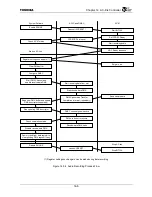
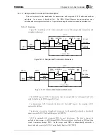
Figure 14.3.5 shows the conceptual sequence of AC-link start-up.
The ACLC Control Enable Register’s Enable AC-link bit is used to deassert/assert the ACRESET*
signal to the link side (including AC-link). This bit defaults to ‘0’, so the CPU asserts the ACRESET*
signal when it boots up.
The AC’97 specification requires that the reset assertion period is 1
µ
s or longer. The software is
responsible for controlling the length of this period.
The AC’97 specification also requires that the primary CODEC stops the AC-link clock (BITCLK)
signal during the period from ACRESET* signal assertion to 162.8ns after ACRESET* signal
deassertion. ACLC assumes the primary CODEC meet this requirement.
Deasserting the link-side reset makes the primary CODEC start driving the BITCLK signal. When
the BITCLK signal is provided, ACLC starts the SYNC signal output, which indicates the start of the
AC-link frame, and starts the frame-length counting.
When a CODEC becomes ready to receive access to its own register, the CODEC sets the “CODEC
Ready” bit of the Tag slot. When ACLC detects that this bit has been set, the ACLC Interrupt Status
Register (ACINTSTS)’s CODEC[1:0] Ready (CODEC[1:0]RDY) bit is set. The system software is
able to recognize the readiness of the CODEC(s) by detecting this event by way of either polling or
interrupt.
In case of 5.1 channel audio connection example (Figure 14.3.2), because the secondary CODEC is
connected to the
SDIN1
signal of ACLC, the software must watch ACINTSTS.CODEC1RDY bit to
determine the CODEC’s readiness for the register access.
Figure 14.3.5 Cold Reset and CODEC Ready Recognition
SDIN
ACRESET
*
BITCLK
SYNC
ENLINK
CODECRDY
ACLC internal clock becomes active
Software sets ENLINK bit
CODEC becomes ready to accept register access
Boot up
Note: The number of BITCLK cycles relative to other signals is not to scale.
Summary of Contents for TMPR4925
Page 1: ...64 Bit TX System RISC TX49 Family TMPR4925 Rev 3 0 ...
Page 4: ......
Page 15: ...Handling Precautions ...
Page 16: ......
Page 18: ...1 Using Toshiba Semiconductors Safely 1 2 ...
Page 40: ...3 General Safety Precautions and Usage Considerations 3 18 ...
Page 42: ...4 Precautions and Usage Considerations 4 2 ...
Page 43: ...TMPR4925 ...
Page 44: ......
Page 54: ...Chapter 1 Features 1 8 ...
Page 58: ...Chapter 2 Block Diagram 2 4 ...
Page 88: ...Chapter 4 Address Mapping 4 12 ...
Page 226: ...Chapter 8 DMA Controller 8 58 ...
Page 260: ...Chapter 9 SDRAM Controller 9 34 ...
Page 480: ...Chapter 15 Interrupt Controller 15 32 ...
Page 554: ...Chapter 19 Real Time Clock RTC 19 8 ...
Page 555: ...Chapter 20 Removed 20 1 20 Removed ...
Page 556: ...Chapter 20 Removed 20 2 ...
Page 564: ...Chapter 21 Extended EJTAG Interface 21 8 ...
Page 580: ...Chapter 22 Electrical Characteristics 22 16 ...
Page 588: ...Chapter 24 Usage Notes 24 2 ...


