Chapter 10 PCI Controller
10-15
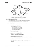
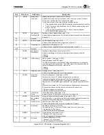
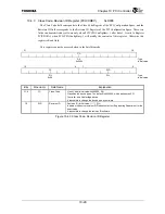
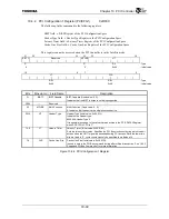
Figure 10.3.8 Transition of the Power Management States
10.3.9 PDMAC (PCI DMA Controller)
The PCI DMA Controller (PDMAC) is a one-channel PCI Director Memory Access (DMA)
controller. Data can be transferred bidirectionally between the G-Bus and the PCI Bus.
10.3.9.1 DMA Transfer
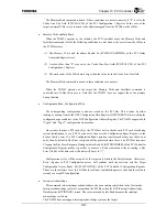
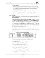
The following DMA transfer procedure does not use the Chain DMA mode.
(1) Address Register and Count Register Setting
Sets values for the three following registers.
•
PDMAC G-Bus Address Register (PDMGA)
•
PDMAC PCI Bus Address Register (PDMPA)
•
PDMAC Count Register (PDMCTR)
(2) Chain
Address
Register
Setting
Sets “0” to the PDMAC Chain Address Register (PDMCA).
(3) PDMAC Status Register (PDMSTATUS) Clearing
Clears any remaining status from a previous DMA transfer.
(4) PDMAC Configuration register (PDMCFG) Setting
Clears the Channel Reset bit (CHRST), and makes settings such as the data transfer direction
(XFRDIRC), and the burst mode (BRSTMD).
(5) DMA
Transfer
Initiation
Setting the Transfer Active bit (XFRACT) of the PDMAC Configuration Register initiates
DMA transfer.
D0
Uninitialized
D0 Active
D3
hot
D3
cold
PCI RST
*
*
(RESET
*
*
)
VCC Cut-off
Software Reset
Power On Reset
(RESET
*
*
)
Initialization by the
System Software
Change PMCSR
PowerState
Summary of Contents for TMPR4925
Page 1: ...64 Bit TX System RISC TX49 Family TMPR4925 Rev 3 0 ...
Page 4: ......
Page 15: ...Handling Precautions ...
Page 16: ......
Page 18: ...1 Using Toshiba Semiconductors Safely 1 2 ...
Page 40: ...3 General Safety Precautions and Usage Considerations 3 18 ...
Page 42: ...4 Precautions and Usage Considerations 4 2 ...
Page 43: ...TMPR4925 ...
Page 44: ......
Page 54: ...Chapter 1 Features 1 8 ...
Page 58: ...Chapter 2 Block Diagram 2 4 ...
Page 88: ...Chapter 4 Address Mapping 4 12 ...
Page 226: ...Chapter 8 DMA Controller 8 58 ...
Page 260: ...Chapter 9 SDRAM Controller 9 34 ...
Page 480: ...Chapter 15 Interrupt Controller 15 32 ...
Page 554: ...Chapter 19 Real Time Clock RTC 19 8 ...
Page 555: ...Chapter 20 Removed 20 1 20 Removed ...
Page 556: ...Chapter 20 Removed 20 2 ...
Page 564: ...Chapter 21 Extended EJTAG Interface 21 8 ...
Page 580: ...Chapter 22 Electrical Characteristics 22 16 ...
Page 588: ...Chapter 24 Usage Notes 24 2 ...

