Chapter 7 External Bus Controller
7-11
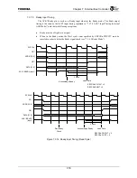
7.3.6.3 Ready
Mode
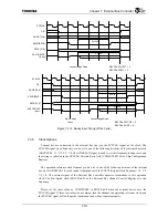
When in this mode, the ACK*/Ready pin becomes Ready input, and the cycle is ended by
Ready input from an external device. Ready input is internally initialized. See Section “7.3.7.5
Ready Input Timing” for more information regarding the operation timing.
When the Wait cycle count specified by EBCCREBCCRn.PWT:WT elapses, a check is
performed to see whether the Ready signal was asserted.
When the number of weight cycles is zero, starts READY check one cycle after CE* is asserted.
In the case except for zero, waits the specified number of cycles and starts READY check.
The Ready mode does not support Burst access by the internal bus.
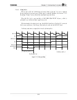
Figure 7.3.3 Ready Mode
SYSCLK
CE
*
ADDR [19:0]
OE
*
DATA [31:0]
ACK
*
/READY
(Input)
EBCCRn.PWT:WT = 2
Start Ready Check
EBCCRn.SHWT = 0
Summary of Contents for TMPR4925
Page 1: ...64 Bit TX System RISC TX49 Family TMPR4925 Rev 3 0 ...
Page 4: ......
Page 15: ...Handling Precautions ...
Page 16: ......
Page 18: ...1 Using Toshiba Semiconductors Safely 1 2 ...
Page 40: ...3 General Safety Precautions and Usage Considerations 3 18 ...
Page 42: ...4 Precautions and Usage Considerations 4 2 ...
Page 43: ...TMPR4925 ...
Page 44: ......
Page 54: ...Chapter 1 Features 1 8 ...
Page 58: ...Chapter 2 Block Diagram 2 4 ...
Page 88: ...Chapter 4 Address Mapping 4 12 ...
Page 226: ...Chapter 8 DMA Controller 8 58 ...
Page 260: ...Chapter 9 SDRAM Controller 9 34 ...
Page 480: ...Chapter 15 Interrupt Controller 15 32 ...
Page 554: ...Chapter 19 Real Time Clock RTC 19 8 ...
Page 555: ...Chapter 20 Removed 20 1 20 Removed ...
Page 556: ...Chapter 20 Removed 20 2 ...
Page 564: ...Chapter 21 Extended EJTAG Interface 21 8 ...
Page 580: ...Chapter 22 Electrical Characteristics 22 16 ...
Page 588: ...Chapter 24 Usage Notes 24 2 ...

