Chapter 11 Serial I/O Port
11-11
11.3.11 Error Detection/Interrupt Signaling
An interrupt is signaled if an error or an interrupt cause is detected, the corresponding status bit is set
and the corresponding Interrupt Enable bit is set.
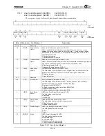
Figure 11.3.3 shows the relationship between the status bit for each interrupt cause and each interrupt
enable bit. Please refer to the explanation for each status bit for more information about each interrupt
cause.
Figure 11.3.3 Relationship Between Interrupt Status Bits and Interrupt Signals
Transmission DMA Acknowledge
Reception DMA Acknowledge
Transmission DMA Acknowledge
SIDICR.TIE
SIDICR.RDE
SIDSR.TDIS
SIDISR.RDIS
SIDISR.TOUT
SIDICR.RIE
SIDICR.SPIE
SIDISR.ERI
To IRC
SIDISR.STIS
SIDICR.CTSAC
CTS Pin
“0” Write
SIDICR.STIE[5]
SISCISR.OERS
SIDICR.TDE
R
“0” Write
DMAC
R
SIDICR.STIE[4]
SISCISR.CTSS
S
SISCISR.RBRKD
SIDICR.STIE[3]
SISCISR.TRDY
SIDICR.STIE[2]
SISCISR.TXALS
SIDICR.STIE[1]
“0” Write
SISCISR.UBRKD
R
SIDICR.STIE[0]
“0” Write
R
“0” Write
R
R
“0” Write
R
“0” Write
DMAC
Transmission DMA Request
Transmission Data Empty
Frame Error
Overrun Error
CTS Status
During Break Reception
Transmission Complete
Transmission Data Empty
Break Detected
Parity Error
Reception Time Out
Reception Data Full
Summary of Contents for TMPR4925
Page 1: ...64 Bit TX System RISC TX49 Family TMPR4925 Rev 3 0 ...
Page 4: ......
Page 15: ...Handling Precautions ...
Page 16: ......
Page 18: ...1 Using Toshiba Semiconductors Safely 1 2 ...
Page 40: ...3 General Safety Precautions and Usage Considerations 3 18 ...
Page 42: ...4 Precautions and Usage Considerations 4 2 ...
Page 43: ...TMPR4925 ...
Page 44: ......
Page 54: ...Chapter 1 Features 1 8 ...
Page 58: ...Chapter 2 Block Diagram 2 4 ...
Page 88: ...Chapter 4 Address Mapping 4 12 ...
Page 226: ...Chapter 8 DMA Controller 8 58 ...
Page 260: ...Chapter 9 SDRAM Controller 9 34 ...
Page 480: ...Chapter 15 Interrupt Controller 15 32 ...
Page 554: ...Chapter 19 Real Time Clock RTC 19 8 ...
Page 555: ...Chapter 20 Removed 20 1 20 Removed ...
Page 556: ...Chapter 20 Removed 20 2 ...
Page 564: ...Chapter 21 Extended EJTAG Interface 21 8 ...
Page 580: ...Chapter 22 Electrical Characteristics 22 16 ...
Page 588: ...Chapter 24 Usage Notes 24 2 ...

