Chapter 2 Block Diagram
2-2
Figure 2.1.1 shows a diagram of the TX4925. The each block is itemized below.
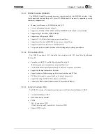
(1) TX49/H2
core
•
It is composed of CPU, System Control Coprocessor (CP0), Instruction Cache, Data Cache,
Floating-Point Unit (FPU), Write Buffer (WBU), Debug Support Unit (DSU) and G-Bus I/F.
−
FPU: IEEE754 compatible single and double precision FPU
It is assigned as one of the coprocessor unit, CP1.
−
I-Cache: Instruction Cache Memory, 16Kbyte, 4-Way set associative
−
D-Cache: Data Cache Memory, 16Kbyte, 4-Way set associative Select write-back mode or
write-through(no write allocate/write allocate) mode for cache write policy.
−
DSU: Debug Support Unit, It is used for on chip debugging module.
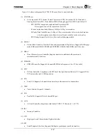
(2) EBUSC
•
External Bus Controller, Provides 6-channels programmable Chip Selects, Supports ROMs (page-
mode ROM, mask ROM, EPROM and EEPROM), SRAMs, flash ROMs and I/O devices
(3) DMAC
•
Direct Memory Access Controller, Supports transfers to and from both memory and
internal/external I/O devices
(4) SDRAMC
•
SDRAM Controller, Supports 4-channels/80 MHz bus frequencies/16 or 32 bus width
(5) PCIC
•
PCI-bus Controller, Compliance with PCI Local Bus Specification Revision 2.2, Supports 32-bit
PCI bus interface and 33 MHz operation
(6) SIO
•
Serial I/O, Supports 2-channels for universal asynchronous receiver/transmitters
(7) TMR
•
Timer/Counter, Supports 3-channels
(8) PIO
•
Parallel I/O, Supports 32-bit of shared PIO pins
(9) ACLC
•
AC-Link Controller, Compliance with Audio CODEC ’97 Revision 2.1 (AC ’97)
(10) IRC
•
Interrupt Controller
(11) CHI
•
High–speed serial Concentration Highway Interface
(12) SPI
•
Serial Peripheral Interface, Supports full-duplex synchronous serial data transfers
Summary of Contents for TMPR4925
Page 1: ...64 Bit TX System RISC TX49 Family TMPR4925 Rev 3 0 ...
Page 4: ......
Page 15: ...Handling Precautions ...
Page 16: ......
Page 18: ...1 Using Toshiba Semiconductors Safely 1 2 ...
Page 40: ...3 General Safety Precautions and Usage Considerations 3 18 ...
Page 42: ...4 Precautions and Usage Considerations 4 2 ...
Page 43: ...TMPR4925 ...
Page 44: ......
Page 54: ...Chapter 1 Features 1 8 ...
Page 58: ...Chapter 2 Block Diagram 2 4 ...
Page 88: ...Chapter 4 Address Mapping 4 12 ...
Page 226: ...Chapter 8 DMA Controller 8 58 ...
Page 260: ...Chapter 9 SDRAM Controller 9 34 ...
Page 480: ...Chapter 15 Interrupt Controller 15 32 ...
Page 554: ...Chapter 19 Real Time Clock RTC 19 8 ...
Page 555: ...Chapter 20 Removed 20 1 20 Removed ...
Page 556: ...Chapter 20 Removed 20 2 ...
Page 564: ...Chapter 21 Extended EJTAG Interface 21 8 ...
Page 580: ...Chapter 22 Electrical Characteristics 22 16 ...
Page 588: ...Chapter 24 Usage Notes 24 2 ...


