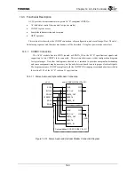
Chapter 14 AC-link Controller
14-5
14.3.3 Usage
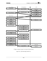
Flow
This section outlines a process flow when using the AC’97 connected to ACLC. Refer to the
subsequent sections for the details of each operation performed in this process flow. The diagrams
below describe the audio playback and recording processes. The modem transmission and reception
can be done in a similar way.
(
*
) Register settings such as volume can be made during data playback.
Figure 14.3.3 Audio Playback Process Flow
Start up AC-link
Register setting such as Volume (
*
)
Enable ENLINK
Check AC’97 status
Setup DMA buffer
Configure DMAC
Start DMA Channel and
enable transmit-data DMA
Deassert ACRESET
*
CODECRDY Interrupt
Start BITCLK
Set CODEC Ready
DAC Ready response
Set volume, etc.
Start transmit-data DMA
Start sending data to slot
DMAC generates Transfer
Completion interrupt (repeatedly)
Write to DMA buffer and update
DMA descriptor (repeatedly)
Stop updating DMA descriptor
DMAC channel goes inactive
DMA underrun error occurs
Stop transmit-data DMA
Stop sending data to slot
Check completion status
Disable transmit-data DMA
Dummy write to data register to
clear pending DMA request if any
Disable ENLINK
Assert ACRESET
*
Stop BITCLK
Stop AC-link
Start audio playback
Stop audio playback
System Software
ACLC and DMAC
AC’97
Summary of Contents for TMPR4925
Page 1: ...64 Bit TX System RISC TX49 Family TMPR4925 Rev 3 0 ...
Page 4: ......
Page 15: ...Handling Precautions ...
Page 16: ......
Page 18: ...1 Using Toshiba Semiconductors Safely 1 2 ...
Page 40: ...3 General Safety Precautions and Usage Considerations 3 18 ...
Page 42: ...4 Precautions and Usage Considerations 4 2 ...
Page 43: ...TMPR4925 ...
Page 44: ......
Page 54: ...Chapter 1 Features 1 8 ...
Page 58: ...Chapter 2 Block Diagram 2 4 ...
Page 88: ...Chapter 4 Address Mapping 4 12 ...
Page 226: ...Chapter 8 DMA Controller 8 58 ...
Page 260: ...Chapter 9 SDRAM Controller 9 34 ...
Page 480: ...Chapter 15 Interrupt Controller 15 32 ...
Page 554: ...Chapter 19 Real Time Clock RTC 19 8 ...
Page 555: ...Chapter 20 Removed 20 1 20 Removed ...
Page 556: ...Chapter 20 Removed 20 2 ...
Page 564: ...Chapter 21 Extended EJTAG Interface 21 8 ...
Page 580: ...Chapter 22 Electrical Characteristics 22 16 ...
Page 588: ...Chapter 24 Usage Notes 24 2 ...

