Chapter 14 AC-link Controller
14-6
(
*
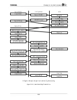
) Register settings such as gain can be made during data recording
Figure 14.3.4 Audio Recording Process Flow
Start up AC-link
Register setting such as gain (
*
)
Enable ENLINK
Check AC’97 status
Clear DMA buffer
Configure DMAC
Start DMA Channel and
enable receive-data DMA
Deassert ACRESET
*
CODECRDY Interrupt
Start BITCLK
Set CODEC Ready
ADC Ready response
Set gain, etc.
Start receiving data from slot
Start receive-data DMA
DMAC generates Transfer
Completion interrupt (repeatedly)
Read from DMA buffer and update
DMA descriptor (repeatedly)
Stop updating DMA descriptor
DMAC channel goes inactive
DMA overrun error occurs
Receive-data DMA halts
Check completion status
Disable receive-data DMA
Dummy read from data register to
clear pending DMA request if any
Disable ENLINK
Assert ACRESET
*
Stop BITCLK
Stop AC-link
Send sample data
System Software
ACLC and DMAC
AC’97
Start recording audio
Summary of Contents for TMPR4925
Page 1: ...64 Bit TX System RISC TX49 Family TMPR4925 Rev 3 0 ...
Page 4: ......
Page 15: ...Handling Precautions ...
Page 16: ......
Page 18: ...1 Using Toshiba Semiconductors Safely 1 2 ...
Page 40: ...3 General Safety Precautions and Usage Considerations 3 18 ...
Page 42: ...4 Precautions and Usage Considerations 4 2 ...
Page 43: ...TMPR4925 ...
Page 44: ......
Page 54: ...Chapter 1 Features 1 8 ...
Page 58: ...Chapter 2 Block Diagram 2 4 ...
Page 88: ...Chapter 4 Address Mapping 4 12 ...
Page 226: ...Chapter 8 DMA Controller 8 58 ...
Page 260: ...Chapter 9 SDRAM Controller 9 34 ...
Page 480: ...Chapter 15 Interrupt Controller 15 32 ...
Page 554: ...Chapter 19 Real Time Clock RTC 19 8 ...
Page 555: ...Chapter 20 Removed 20 1 20 Removed ...
Page 556: ...Chapter 20 Removed 20 2 ...
Page 564: ...Chapter 21 Extended EJTAG Interface 21 8 ...
Page 580: ...Chapter 22 Electrical Characteristics 22 16 ...
Page 588: ...Chapter 24 Usage Notes 24 2 ...

