Chapter 17 Serial Peripheral Interface
17-1
17. Serial Peripheral Interface
17.1 Characteristics
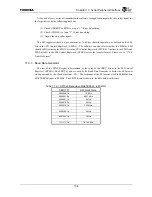
The SPI is a serial interface consisting of clock, data out, and data in. The SPI is used to interface to
devices such as serial power supplies, serial A/D converters, and other devices that contain simple serial
clock and data interface. The TX4925 only supports the master mode and generates the SPI clock to the
slaves. Multiple slave devices can share the SPI by using a unique chip select for each slave device. The
chip select can be generated using one of the general purpose I/O ports on TX4925, or using some other
output port available in the system. When a device is selected by asserting it’s chip select, the device will
shift data in using the SPICLK and SPIOUT signals and the device will shift data out using the SPIIN signal.
When a device is not selected then the data output connected to SPIIN must be tri-stated so other devices can
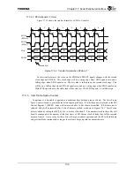
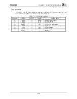
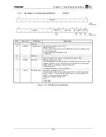
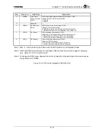
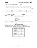
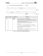
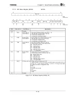
share the SPIIN signal. The SPI module contains registers which provide programmability for SPICLK rate,
MSB first versus LSB first, clock polarity, data phase polarity, and byte mode versus word mode operation.
The SPI has the following characteristics.
•
Phase and Polarity Selection
•
Transfer size of 8 or 16 bits
•
4 frame transmit, 4 frame receive buffers
•
Master operation
•
Inter Frame Space Delay Feature
•
MSB/LSB first transfer
Summary of Contents for TMPR4925
Page 1: ...64 Bit TX System RISC TX49 Family TMPR4925 Rev 3 0 ...
Page 4: ......
Page 15: ...Handling Precautions ...
Page 16: ......
Page 18: ...1 Using Toshiba Semiconductors Safely 1 2 ...
Page 40: ...3 General Safety Precautions and Usage Considerations 3 18 ...
Page 42: ...4 Precautions and Usage Considerations 4 2 ...
Page 43: ...TMPR4925 ...
Page 44: ......
Page 54: ...Chapter 1 Features 1 8 ...
Page 58: ...Chapter 2 Block Diagram 2 4 ...
Page 88: ...Chapter 4 Address Mapping 4 12 ...
Page 226: ...Chapter 8 DMA Controller 8 58 ...
Page 260: ...Chapter 9 SDRAM Controller 9 34 ...
Page 480: ...Chapter 15 Interrupt Controller 15 32 ...
Page 554: ...Chapter 19 Real Time Clock RTC 19 8 ...
Page 555: ...Chapter 20 Removed 20 1 20 Removed ...
Page 556: ...Chapter 20 Removed 20 2 ...
Page 564: ...Chapter 21 Extended EJTAG Interface 21 8 ...
Page 580: ...Chapter 22 Electrical Characteristics 22 16 ...
Page 588: ...Chapter 24 Usage Notes 24 2 ...

