Chapter 10 PCI Controller
10-51
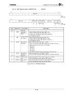
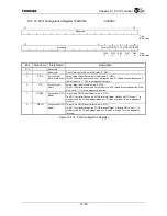
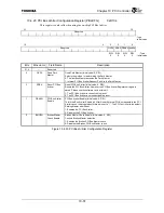
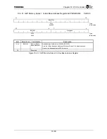
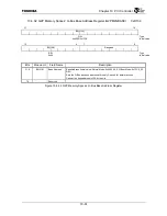
10.4.23 PCI Bus Arbiter Configuration Register (PBACFG)
0xD104
This register is only valid when using the on-chip PCI Bus Arbiter.
31
16
Reserved
:
Type
: Initial value
15
4
3
2
1
0
Reserved FIXPA RPBA
PBAEN
BMCEN
R/W
R/W
R/W
R/W
:
Type
0
0
0
0
:
Initial
value
Bits Mnemonic Field
Name
Description
31:4
⎯
Reserved
⎯
3 FIXPA
Fixed Park
Master
Fixed Park Master (Initial value: 0, R/W)
Selects the method for determining the Park Master.
0: The last Bus Master becomes the Park Master.
1: Internal PCI Bus Arbiter Request Port A is the Park Master.
2 RPBA
Reset PCI Bus
Arbiter
Reset PCI Bus Arbiter (Initial value: 0, R/W)
Resets the PCI Bus Arbiter. However, the PCI Bus Arbiter Register settings are
saved. Please use the software to clear this bit.
1: The PCI Bus Arbiter is currently being reset.
0: The PCI Bus Arbiter is not currently being reset.
1 PBAEN
PCI Bus Arbiter
Enable
PCI Bus Arbiter Enable (Initial value: 0, R/W)
This is the Bus Arbiter Enable bit. After Reset, External PCI Bus requests to the PCI
Arbiter cannot be accepted until this bit is set to “1”. The PCI Controller is the default
Parking Master after Reset.
1: Enables the PCI Bus Arbiter.
0: Disables the PCI Bus Arbiter.
0 BMCEN
Broken Master
Check Enable
Broken Master Check Enable (Initial value: 0, R/W)
Controls Broken Master detection.
1: Enables the Broken PCI Bus Master check.
0: Disables the Broken PCI Bus Master check.
Figure 10.4.23 PCI Bus Arbiter Configuration Register
Summary of Contents for TMPR4925
Page 1: ...64 Bit TX System RISC TX49 Family TMPR4925 Rev 3 0 ...
Page 4: ......
Page 15: ...Handling Precautions ...
Page 16: ......
Page 18: ...1 Using Toshiba Semiconductors Safely 1 2 ...
Page 40: ...3 General Safety Precautions and Usage Considerations 3 18 ...
Page 42: ...4 Precautions and Usage Considerations 4 2 ...
Page 43: ...TMPR4925 ...
Page 44: ......
Page 54: ...Chapter 1 Features 1 8 ...
Page 58: ...Chapter 2 Block Diagram 2 4 ...
Page 88: ...Chapter 4 Address Mapping 4 12 ...
Page 226: ...Chapter 8 DMA Controller 8 58 ...
Page 260: ...Chapter 9 SDRAM Controller 9 34 ...
Page 480: ...Chapter 15 Interrupt Controller 15 32 ...
Page 554: ...Chapter 19 Real Time Clock RTC 19 8 ...
Page 555: ...Chapter 20 Removed 20 1 20 Removed ...
Page 556: ...Chapter 20 Removed 20 2 ...
Page 564: ...Chapter 21 Extended EJTAG Interface 21 8 ...
Page 580: ...Chapter 22 Electrical Characteristics 22 16 ...
Page 588: ...Chapter 24 Usage Notes 24 2 ...

