Chapter 3 Signals
3-2
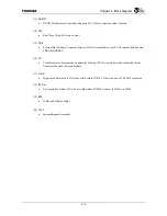
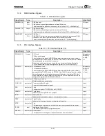
3.1.2
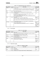
SDRAM Interface Signals
Table 3.1.2 SDRAM Interface Signals
Signal Name
Type
Description
Initial State
SDCLK[1:0]
Output
SDRAM Controller Clock
Clock signals used by SDRAM/SyncFlash. The clock frequency is the same as the G-
Bus clock (GBUSCLK) frequency.
When these clock signals are not used, the pins can be set to L using the SDCLK
Enable field of the pin configuration register (PCFG.SDCLKEN[1:0]).
All High
SDCLKIN
Input/output
SDRAM Feedback Clock input
Feedback clock signal for SDRAM controller input signals.
Input
CKE Output
Clock
Enable
CKE signal for SDRAM/SyncFlash.
High
SDCS[3:0]
*
Output
Synchronous Memory Device Chip Select
Chip select signals for SDRAM/SyncFlash.
All High
RAS
*
Output
Row Address Strobe
RAS signal for SDRAM/SyncFlash.
High
CAS
*
Output
Column
Address
Strobe
CAS signal for SDRAM/SyncFlash.
High
WE
*
Output
Write
Enable
WR signal for SDRAM/SyncFlash.
High
DQM[3:0] Output
Data
Mask
During a write cycle, the DQM signals function as a data mask. During a read cycle,
they control the SDRAM output buffers. The bits correspond to the following data bus
signals:
DQM[3]:DATA[31:24], DQM[2]:DATA[23:16]
DQM[1]:DATA[15:8], DQM[0]:DATA[7:0]
All High
RP
*
Output
This pin should be left open.
Low
Summary of Contents for TMPR4925
Page 1: ...64 Bit TX System RISC TX49 Family TMPR4925 Rev 3 0 ...
Page 4: ......
Page 15: ...Handling Precautions ...
Page 16: ......
Page 18: ...1 Using Toshiba Semiconductors Safely 1 2 ...
Page 40: ...3 General Safety Precautions and Usage Considerations 3 18 ...
Page 42: ...4 Precautions and Usage Considerations 4 2 ...
Page 43: ...TMPR4925 ...
Page 44: ......
Page 54: ...Chapter 1 Features 1 8 ...
Page 58: ...Chapter 2 Block Diagram 2 4 ...
Page 88: ...Chapter 4 Address Mapping 4 12 ...
Page 226: ...Chapter 8 DMA Controller 8 58 ...
Page 260: ...Chapter 9 SDRAM Controller 9 34 ...
Page 480: ...Chapter 15 Interrupt Controller 15 32 ...
Page 554: ...Chapter 19 Real Time Clock RTC 19 8 ...
Page 555: ...Chapter 20 Removed 20 1 20 Removed ...
Page 556: ...Chapter 20 Removed 20 2 ...
Page 564: ...Chapter 21 Extended EJTAG Interface 21 8 ...
Page 580: ...Chapter 22 Electrical Characteristics 22 16 ...
Page 588: ...Chapter 24 Usage Notes 24 2 ...

