Chapter 14 AC-link Controller
14-23
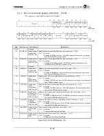
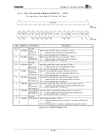
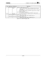
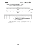
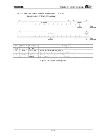
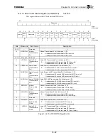
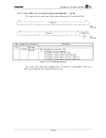
14.4.4 ACLC Interrupt Status Register (ACINTSTS)
0xF710
This register shows various kinds of AC-link and ACLC status.
31
16
Reserved
: Type
:
Initial
value
15
14
13
12
11
10 9 8 7 6 5 4 3 2 1 0
MODIE
RR
MODOE
RR
Reserved
AUDIE
RR
LFEERR
CENTE
RR
SURRE
RR
AUDOE
RR
Reserved
GPIOINT
REGAC
CRDY
Reserved
CODEC
1RDY
CODEC
0RDY
R/W1C R/W1C
R/W1C
R/W1C
R/W1C
R/W1C R/W1C
R/W1C R/W1C
R
R
:
Type
0 0 0 0 0 0 0 0 1 0 0
:
Initial
value
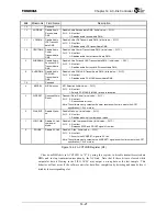
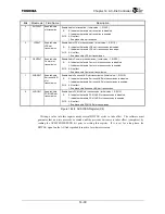
Bits Mnemonic Field
Name
Description
31:16 —
Reserved
—
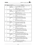
Modem Receive-data DMA Overrun (Initial value: 0, R/W1C)
15 MODIERR
Modem
Receive-data
DMA Overrun
R
W1C
1: Indicates that the modem receive-data DMA overran.
This bit is cleared when “1” is written to it.
Modem Transmit-data DMA Underrun (Initial value: 0, R/W1C)
14 MODOERR
Modem
Transmit-data
DMA Underrun
R
W1C
1: Indicates that the modem transmit-data DMA underran.
This bit is cleared when “1” is written to it.
13
⎯
Reserved
—
Audio Receive-data DMA Overrun (Initial value: 0, R/W1C)
12 AUDIERR
Audio
Receive-data
DMA Overrun
R
W1C
1: Indicates that the audio receive-data DMA overran.
This bit is cleared when “1” is written to it.
Audio LFE Transmit-data DMA Underrun (Initial value: 0, R/W1C)
11 LFEERR
Audio LFE
Transmit-data
DMA Underrun
R
W1C
1: Indicates that the audio LFE transmit-data DMA underran.
This bit is cleared when “1” is written to it.
Audio Center Transmit-data DMA Underrun (Initial value: 0, R/W1C)
10 CENTERR
Audio Center
Transmit-data
DMA Underrun
R
W1C
1: Indicates that the audio center transmit-data DMA underran.
This bit is cleared when “1” is written to it.
Audio Surround L&R Transmit-data DMA Underrun (Initial value: 0, R/W1C)
9 SURRERR
Audio Surround
L&R
Transmit-data
DMA Underrun
R
W1C
1: Indicates that the audio surround L&R transmit-data DMA underran.
This bit is cleared when “1” is written to it.
Audio PCM L&R Transmit-data DMA Underrun (Initial value: 0, R/W1C)
8 AUDOERR
Audio PCM L&R
Transmit-data
DMA Underrun
R
W1C
1: Indicates that the audio PCM L&R transmit-data DMA underran.
This bit is cleared when “1” is written to it.
7:6
⎯
Reserved
—
GPIO Interrupt (Initial value: 0, R/W1C)
5 GPIOINT
GPIO
Interrupt
R
W1C
1: Indicates that the incoming slot 12 bit[0] is ‘1’ (the modem CODEC GPIO
interrupt).
This bit is cleared if “1” is written to it while the incoming slot 12 bit[0] is ‘0’.
Figure 14.4.4 ACINTSTS Register (1/2)
Summary of Contents for TMPR4925
Page 1: ...64 Bit TX System RISC TX49 Family TMPR4925 Rev 3 0 ...
Page 4: ......
Page 15: ...Handling Precautions ...
Page 16: ......
Page 18: ...1 Using Toshiba Semiconductors Safely 1 2 ...
Page 40: ...3 General Safety Precautions and Usage Considerations 3 18 ...
Page 42: ...4 Precautions and Usage Considerations 4 2 ...
Page 43: ...TMPR4925 ...
Page 44: ......
Page 54: ...Chapter 1 Features 1 8 ...
Page 58: ...Chapter 2 Block Diagram 2 4 ...
Page 88: ...Chapter 4 Address Mapping 4 12 ...
Page 226: ...Chapter 8 DMA Controller 8 58 ...
Page 260: ...Chapter 9 SDRAM Controller 9 34 ...
Page 480: ...Chapter 15 Interrupt Controller 15 32 ...
Page 554: ...Chapter 19 Real Time Clock RTC 19 8 ...
Page 555: ...Chapter 20 Removed 20 1 20 Removed ...
Page 556: ...Chapter 20 Removed 20 2 ...
Page 564: ...Chapter 21 Extended EJTAG Interface 21 8 ...
Page 580: ...Chapter 22 Electrical Characteristics 22 16 ...
Page 588: ...Chapter 24 Usage Notes 24 2 ...

