Chapter 9 SDRAM Controller
9-1
9. SDRAM
Controller
9.1 Characteristics
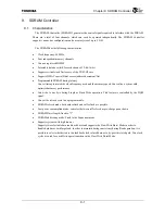
The SDRAM Controller (SDRAMC) generates the control signals required to interface with the SDRAM.
There are a total of four channels, which can each be operated independently. The SDRAM Controller
supports various bus configurations and a memory size of up to 2 GB.
The SDRAM has the following characteristics.
•
Clock frequency: 80 MHz
•
Four independent memory channels
•
Can use registered DIMM
•
Selectable data bus width for each channel: 32-bit/16-bit
•
Supports critical word first access of the TX49/H2 core
•
Supports DMAC special Burst access (address decrement/fix)
•
Programmable SDRAM timing latency
Can set timing to match the clock frequency used and the memory speed. Can realize a system with
optimized memory performance.
•
Can write to any byte during Single or Burst Write operation. This feature is controlled by the DQM
signal.
•
Can set the refresh cycle to be programmable.
•
SDRAM refresh mode: both auto refresh and self refresh are possible.
•
Low power consumption mode: can select between self refresh or pre-charge power down
•
SDRAM Burst length: fixed to "2"
•
SDRAM addressing mode: Fixed to the Sequential mode
•
Supports systems with high fan-out
Supports two selectable data read-back buses and supports the Slow Write Burst Mode in order to
handle data buses with large load. In order to maintain timing consistency during Read operation, it is
possible to select whether to use the feedback clock to latch data or to by-pass this latch path. Two clock
cycles are used for each Write operation when in the Slow Write Burst Mode.
Summary of Contents for TMPR4925
Page 1: ...64 Bit TX System RISC TX49 Family TMPR4925 Rev 3 0 ...
Page 4: ......
Page 15: ...Handling Precautions ...
Page 16: ......
Page 18: ...1 Using Toshiba Semiconductors Safely 1 2 ...
Page 40: ...3 General Safety Precautions and Usage Considerations 3 18 ...
Page 42: ...4 Precautions and Usage Considerations 4 2 ...
Page 43: ...TMPR4925 ...
Page 44: ......
Page 54: ...Chapter 1 Features 1 8 ...
Page 58: ...Chapter 2 Block Diagram 2 4 ...
Page 88: ...Chapter 4 Address Mapping 4 12 ...
Page 226: ...Chapter 8 DMA Controller 8 58 ...
Page 260: ...Chapter 9 SDRAM Controller 9 34 ...
Page 480: ...Chapter 15 Interrupt Controller 15 32 ...
Page 554: ...Chapter 19 Real Time Clock RTC 19 8 ...
Page 555: ...Chapter 20 Removed 20 1 20 Removed ...
Page 556: ...Chapter 20 Removed 20 2 ...
Page 564: ...Chapter 21 Extended EJTAG Interface 21 8 ...
Page 580: ...Chapter 22 Electrical Characteristics 22 16 ...
Page 588: ...Chapter 24 Usage Notes 24 2 ...

