3 General Safety Precautions and Usage Considerations
3-13
(2) Using medium infrared ray reflow
•
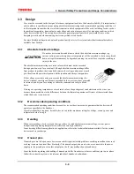
Heating top and bottom with long or medium infrared rays is recommended (see Figure 3).
Long infrared ray heater (preheating)
Medium infrared ray heater
(reflow)
Product flow
Figure 3 Heating top and bottom with long or medium infrared rays
•
Complete the infrared ray reflow process from 30 to 50 seconds at a package surface temperature of between
210°C and 260°C.
•
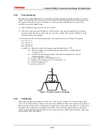
Refer to Figure 4 for an example of a good temperature profile for infrared or hot air reflow.
230
30-50 s
Time (s)
60-120 s
(°C)
260
190
180
P
a
ckage
surface tem
p
erature
Figure 4 Sample temperature profile for infrared or hot air reflow
(3) Using hot air reflow
•
Complete hot air reflow from 30 to 50 seconds at a package surface temperature of between 230°C and
260°C.
•
For an example of a recommended temperature profile, refer to Figure 4 above.
3.5.4
Flux cleaning and ultrasonic cleaning
(1) When cleaning circuit boards to remove flux, make sure that no residual reactive ions such as Na or Cl
remain. Note that organic solvents react with water to generate hydrogen chloride and other corrosive gases
which can degrade device performance.
(2) Washing devices with water will not cause any problems. However, make sure that no reactive ions such as
sodium and chlorine are left as a residue. Also, be sure to dry devices sufficiently after washing.
(3) Do not rub device markings with a brush or with your hand during cleaning or while the devices are still
wet from the cleaning agent. Doing so can rub off the markings.
Summary of Contents for TMPR4925
Page 1: ...64 Bit TX System RISC TX49 Family TMPR4925 Rev 3 0 ...
Page 4: ......
Page 15: ...Handling Precautions ...
Page 16: ......
Page 18: ...1 Using Toshiba Semiconductors Safely 1 2 ...
Page 40: ...3 General Safety Precautions and Usage Considerations 3 18 ...
Page 42: ...4 Precautions and Usage Considerations 4 2 ...
Page 43: ...TMPR4925 ...
Page 44: ......
Page 54: ...Chapter 1 Features 1 8 ...
Page 58: ...Chapter 2 Block Diagram 2 4 ...
Page 88: ...Chapter 4 Address Mapping 4 12 ...
Page 226: ...Chapter 8 DMA Controller 8 58 ...
Page 260: ...Chapter 9 SDRAM Controller 9 34 ...
Page 480: ...Chapter 15 Interrupt Controller 15 32 ...
Page 554: ...Chapter 19 Real Time Clock RTC 19 8 ...
Page 555: ...Chapter 20 Removed 20 1 20 Removed ...
Page 556: ...Chapter 20 Removed 20 2 ...
Page 564: ...Chapter 21 Extended EJTAG Interface 21 8 ...
Page 580: ...Chapter 22 Electrical Characteristics 22 16 ...
Page 588: ...Chapter 24 Usage Notes 24 2 ...

