Chapter 15 Interrupt Controller
15-6
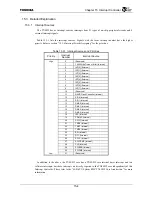
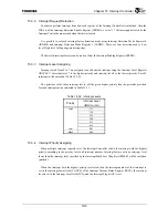
Priorities are assigned as follows.
•
When interrupt levels differ, the interrupt with the higher interrupt level has priority (Table
15.3.2)
•
When multiple interrupts with the same interrupt level are simultaneously detected, the
interrupt with the smaller interrupt number has priority (Table 15.3.1).
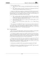
In addition, the interrupt priority assignments are reevaluated under the following conditions. When a
new interrupt is generated until the reevaluation timing, the interrupt with the highest priority of all
interrupts including a new one is selected and the Interrupt Factor field (CAUSE) and Interrupt Level
field (LVL) of the Interrupt Current Status Register (IRCS) are set again.
•
When an interrupt request with a higher interrupt level than that of the currently selected
interrupt is detected. However, when the interrupt levels are equal, the Interrupt factor field
(CAUSE) does not change even if the interrupt number is small.
•
When the interrupt level (IRLVLn.ILm) of the currently selected interrupt changes to a value
smaller than the current setting.
•
When the currently selected interrupt is cleared (refer to “15.3.6 Clearing Interrupt
Requests”).
If the interrupt mask level (IRMSK.IML) changes to a value, the interrupt priority assignments are
not reevaluated. However, when the interrupt mask level (IRMSK.IML) changes to a value equal to or
larger than the currently selected interrupt level (IRLVLn.ILM), the interrupt flag bit of the interrupt
current status register (IRCS.IF) is set to "1", and the interrupt is masked.
15.3.5 Interrupt
Notification
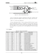
When the interrupt with the highest priority is selected, then the interrupt factor is reported to the
Interrupt Current Status Register (IRCS) and an interrupt is reported to the TX49/H2 core.
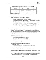
The TX49/H2 core distinguishes interrupt factors using the IP field (IP[7:2]) of the Cause Register.
The interrupt notification from the Interrupt Controller is reflected in the IP[2] bit. The Interrupt
Handler uses the IP[2] bit to judge whether or not there are interrupts from this Interrupt Controller and
uses the Interrupt Current Status Register (IRCS) to determine the interrupt cause.
The Interrupt Factor field (IRCS.CAUSE) value is reflected in the remaining bits of the IP field.
Since bit IP[7] is also being used for notification of TX49/H2 CPU core internal timer interrupts, the
contents specified by IP[7] differ according to whether internal timer interrupts are set to valid
(TINTDIS=0) or invalid (TINTDIS=1), as indicated Table 15.3.3.
The Interrupt Factor field (IRCS.CAUSE) value is reflected in the remaining bits of the IP field.
TINTDIS is the value that is set from ADDR[0] at the timing when the RESET* signal is deasserted.
See the explanation “3.3 Pin Multiplexing” for more information.
Summary of Contents for TMPR4925
Page 1: ...64 Bit TX System RISC TX49 Family TMPR4925 Rev 3 0 ...
Page 4: ......
Page 15: ...Handling Precautions ...
Page 16: ......
Page 18: ...1 Using Toshiba Semiconductors Safely 1 2 ...
Page 40: ...3 General Safety Precautions and Usage Considerations 3 18 ...
Page 42: ...4 Precautions and Usage Considerations 4 2 ...
Page 43: ...TMPR4925 ...
Page 44: ......
Page 54: ...Chapter 1 Features 1 8 ...
Page 58: ...Chapter 2 Block Diagram 2 4 ...
Page 88: ...Chapter 4 Address Mapping 4 12 ...
Page 226: ...Chapter 8 DMA Controller 8 58 ...
Page 260: ...Chapter 9 SDRAM Controller 9 34 ...
Page 480: ...Chapter 15 Interrupt Controller 15 32 ...
Page 554: ...Chapter 19 Real Time Clock RTC 19 8 ...
Page 555: ...Chapter 20 Removed 20 1 20 Removed ...
Page 556: ...Chapter 20 Removed 20 2 ...
Page 564: ...Chapter 21 Extended EJTAG Interface 21 8 ...
Page 580: ...Chapter 22 Electrical Characteristics 22 16 ...
Page 588: ...Chapter 24 Usage Notes 24 2 ...

