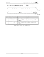
Chapter 19 Real Time Clock (RTC)
19-6
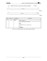
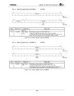
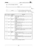
19.4.5 RTC Control Register (RTCCTRL)
0xF910
31
16
Reserved
: Type
:
Initial
value
15 8 7 6 5 4 3 2 1 0
Reserved
DISRTINT DISALINT
FRZPRE FRZRTC RTCCLR Reserved TSTCLK RTCTST
R/W R/W R/W R/W R/W
R/W R/W
:
Type
1 1 0 0 0 0 0
:
Initial
value
Bits Mnemonic Field
Name
Explanation
31:8
⎯
Reserved
⎯
7 DISRTINT
Disable RTC
Interrupt
Disable RTC Interrupt (Initial value: 1, R/W)
Disable RTC Interrupt. If clear, the interrupt occurs when RTC counter reaches a
value of “0xffffffffff”.
1: Disable
0: Enable
6 DISALINT
Disable Alarm
Interrupt
Disable Alarm Interrupt (Initial value: 1, R/W)
Disable Alarm Interrupt. If clear, the interrupt occurs when RTC counter reaches a
value that is equal to the value of Alarm count.
1: Disable
0: Enable
5 FRZPRE
Freeze
Prescaler
Freeze Prescaler (Initial value: 0, R/W)
Setting this bit will cause the lower 8 bits of the RTC counter to freeze. This bit is a
test bit and customers can’t use it.
1: Freeze
0: Run
4 FRZRTC
Freeze
RTC
Freeze RTC (Initial value: 0, R/W)
Setting this bit will cause the upper 36 bits of the RTC counter to freeze. This bit is
a test bit and customers can’t use it.
1: Freeze
0: Run
3 RTCCLR
RTC
Clear RTC Clear (Initial value: 0, R/W)
Setting this bit to a logic “1” will cause all 44 bits of the RTC counter to initialize to
“0x0000000_0000”. The RTC counter will stay cleared and the counter will not start
counting until this bit is cleared back to a logic “0”.
1: Stop
0: Run
2
⎯
Reserved
⎯
1 TSTCLK
Enable
Test
Clock
Enable Test Clock (Initial value: 0, R/W)
Setting this bit will cause the 32 kHz input clock for the RTC counter to be driven by
the IMBUSCLK instead of the 32 kHz input pin. This bit is a test bit and customers
can’t use it.
0: 32 KHz input
1: IMBUSCLK
0
RTCTST
Enable RTC Test Enable RTC Test (Initial value: 0, R/W)
Setting this bit will cause all five of the 8-bit counters and the 4-bit counter that
comprise the RTC counter to count together. This bit is a test bit and customers
can’t use it.
0: Normal run
1: Test run
Figure 19.4.5 RTC Control Register (RTCCTRL)
Summary of Contents for TMPR4925
Page 1: ...64 Bit TX System RISC TX49 Family TMPR4925 Rev 3 0 ...
Page 4: ......
Page 15: ...Handling Precautions ...
Page 16: ......
Page 18: ...1 Using Toshiba Semiconductors Safely 1 2 ...
Page 40: ...3 General Safety Precautions and Usage Considerations 3 18 ...
Page 42: ...4 Precautions and Usage Considerations 4 2 ...
Page 43: ...TMPR4925 ...
Page 44: ......
Page 54: ...Chapter 1 Features 1 8 ...
Page 58: ...Chapter 2 Block Diagram 2 4 ...
Page 88: ...Chapter 4 Address Mapping 4 12 ...
Page 226: ...Chapter 8 DMA Controller 8 58 ...
Page 260: ...Chapter 9 SDRAM Controller 9 34 ...
Page 480: ...Chapter 15 Interrupt Controller 15 32 ...
Page 554: ...Chapter 19 Real Time Clock RTC 19 8 ...
Page 555: ...Chapter 20 Removed 20 1 20 Removed ...
Page 556: ...Chapter 20 Removed 20 2 ...
Page 564: ...Chapter 21 Extended EJTAG Interface 21 8 ...
Page 580: ...Chapter 22 Electrical Characteristics 22 16 ...
Page 588: ...Chapter 24 Usage Notes 24 2 ...

