Chapter 9 SDRAM Controller
9-9
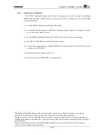
9.3.3 Initialization
of
SDRAM
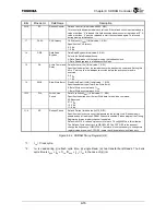
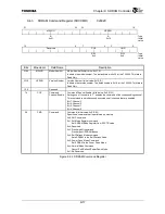
The TX4925 Command Register has functions for generating the cycles required for initializing
SDRAM and SyncFlash. Using software to set each register makes it possible to execute initial settings
at a particular timing.
(1) Set the SDRAM Channel Control Register (SDCCRn).
(2) Set the SDRAM Timing Register (SDCTR). This timing setting is applied to all channels, so please
set it to the slowest memory device.
(3) Use the SDRAM Command Register (SDCCMD) to issue the Pre-charge All command.
(4) Issue the Set Mode Register command in the same manner.
(5) Set the refresh count required to initialize SDRAM to the refresh counter (SDCTR.RC)
1
and set the
refresh cycle (SDCTR.RP).
2
3
(6) Wait until the refresh counter returns to “0.”
(7) Set the refresh cycle (SDCTR.RP) to the proper value.
1
The number of refresh operations can be counted using the refresh counter. With this function, it is no longer
necessary to assemble special timing groups in the software when counting refresh operations.
2
Setting the refresh cycle to a small value makes it possible to expedite completion of the refresh cycle required for
SDRAM initialization. As described above, please set normal values after the required number of refresh cycles have
been generated.
3
Refresh requests have priority over all other SDRAM Controller access requests. Please do not set the memory
refresh cycle to an unnecessarily short value.
Summary of Contents for TMPR4925
Page 1: ...64 Bit TX System RISC TX49 Family TMPR4925 Rev 3 0 ...
Page 4: ......
Page 15: ...Handling Precautions ...
Page 16: ......
Page 18: ...1 Using Toshiba Semiconductors Safely 1 2 ...
Page 40: ...3 General Safety Precautions and Usage Considerations 3 18 ...
Page 42: ...4 Precautions and Usage Considerations 4 2 ...
Page 43: ...TMPR4925 ...
Page 44: ......
Page 54: ...Chapter 1 Features 1 8 ...
Page 58: ...Chapter 2 Block Diagram 2 4 ...
Page 88: ...Chapter 4 Address Mapping 4 12 ...
Page 226: ...Chapter 8 DMA Controller 8 58 ...
Page 260: ...Chapter 9 SDRAM Controller 9 34 ...
Page 480: ...Chapter 15 Interrupt Controller 15 32 ...
Page 554: ...Chapter 19 Real Time Clock RTC 19 8 ...
Page 555: ...Chapter 20 Removed 20 1 20 Removed ...
Page 556: ...Chapter 20 Removed 20 2 ...
Page 564: ...Chapter 21 Extended EJTAG Interface 21 8 ...
Page 580: ...Chapter 22 Electrical Characteristics 22 16 ...
Page 588: ...Chapter 24 Usage Notes 24 2 ...

