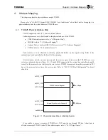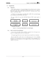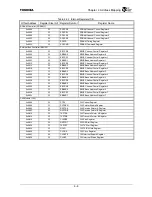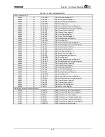
Chapter 3 Signals
3-14
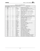
Table 3.2.2 Boot Configuration Specified with the ADDR[19:0], TDO, UAE and SADDR10 Signals (2/2)
Signal Description
Corresponding
Register Bit
Configuration
Determined at
ADDR[8:6]
Select Boot Memory
Selects boot memory.
HHH = Device connected to channel 0 of the external bus controller
(clock frequency division ratio: 1/1)
HHL = Device connected to channel 0 of the external bus controller
(clock frequency division ratio: 1/2)
HLH = Device connected to channel 0 of the external bus controller
(clock frequency division ratio: 1/3)
HLL = Reserved
LHH = PCI boot
LHL = Reserved
LLH = Reserved
LLL = Reserved
EBCCR0.ME
RESET
*
deassert
edge
ADDR[5] Boot
ACK
*
Input
Specifies the access mode for external bus controller channel 0.
L = ACK
*
Input Mode Enable
H = ACK
*
Input Mode Disable
EBCCR0.EACK
RESET
*
deassert
edge
ADDR[4:3] Select SYSCLK Frequency
Specifies the division ratio of the SYSCLK frequency to the G-Bus clock
(GBUSCLK) frequency.
LL = 4 (SYSCLK frequency = GBUSCLK frequency/4)
LH = 3 (SYSCLK frequency = GBUSCLK frequency/3)
HL = 2 (SYSCLK frequency = GBUSCLK frequency/2)
HH = 1 (SYSCLK frequency = GBUSCLK frequency)
CCFG. SYSSP
PON
*
deassert edge
ADDR[2] Reserved
This signal will not be set to 0 upon booting.
⎯
RESET
*
deassert
edge
ADDR[1]
PCI Arbiter Select
Selects a PCI bus arbiter.
L = External PCI bus arbiter.
H = Built-in PCI bus arbiter.
CCFG.PCIARB
RESET
*
deassert
edge
ADDR[0]
TX49/H2 Internal Timer Interrupt Disable
Specifies whether timer interrupts within the TX49/H2 core are enabled.
L = Enable timer interrupts within the TX49/H2 core.
H = Disable timer interrupts within the TX49/H2 core.
CCFG.TINTDIS
RESET
*
deassert
edge
TDO PC
Trace
Specifies whether PIO[31:20] and BC32K are used as PC trace signals.
L = Use as TPC[3:1], PCST[7:0] and DCLK
H = Use as PIO[31:20] and BC32K
CCFG.PCTRCE PON
*
deassert edge
UAE Reserved
Used for testing. Because this signal is used for setting a clock
frequency, ensure that the signal will not be set to 0 upon booting.
CCFG.bit[28]
PON
*
deassert edge
SADDR10 Reserved
Used for testing. Because this signal is used for setting a clock
frequency, ensure that the signal will not be set to 0 upon booting.
⎯
PON
*
deassert edge
Summary of Contents for TMPR4925
Page 1: ...64 Bit TX System RISC TX49 Family TMPR4925 Rev 3 0 ...
Page 4: ......
Page 15: ...Handling Precautions ...
Page 16: ......
Page 18: ...1 Using Toshiba Semiconductors Safely 1 2 ...
Page 40: ...3 General Safety Precautions and Usage Considerations 3 18 ...
Page 42: ...4 Precautions and Usage Considerations 4 2 ...
Page 43: ...TMPR4925 ...
Page 44: ......
Page 54: ...Chapter 1 Features 1 8 ...
Page 58: ...Chapter 2 Block Diagram 2 4 ...
Page 88: ...Chapter 4 Address Mapping 4 12 ...
Page 226: ...Chapter 8 DMA Controller 8 58 ...
Page 260: ...Chapter 9 SDRAM Controller 9 34 ...
Page 480: ...Chapter 15 Interrupt Controller 15 32 ...
Page 554: ...Chapter 19 Real Time Clock RTC 19 8 ...
Page 555: ...Chapter 20 Removed 20 1 20 Removed ...
Page 556: ...Chapter 20 Removed 20 2 ...
Page 564: ...Chapter 21 Extended EJTAG Interface 21 8 ...
Page 580: ...Chapter 22 Electrical Characteristics 22 16 ...
Page 588: ...Chapter 24 Usage Notes 24 2 ...


