Chapter 11 Serial I/O Port
11-5
11.3.3 Serial
Clock
Generator
Generates the Serial Clock (SIOCLK). SIOCLK determines the serial transfer rate and has a
frequency that is 16
×
the baud rate. One of the following can be selected as the source for the Serial
Clock (SIOCLK).
•
Internal System Clock (IMBUSCLKF)
•
External Clock Input (SCLK)
•
Baud rate generator circuit output
The IMBUSCLKF frequency can be selected from frequencies that are 1/5 the frequency of the CPU
clock. The maximum frequency tolerance of the external clock input (SCLK) is 45% the frequency of
IMBUSCLKF. For example, if IMBUSCLKF = 40 MHz, then set SCLK to 18 MHz or less.
The baud rate generator is a circuit that divides these clock signals according to the following
formula.
Baud Rate =
16
×
Divisor
×
Prescalar
fc
•
fc: Clock frequency of IMBUSCLKF or an external clock input (SCLK)
•
Prescalar Value: 2, 8, 32, 128
•
Divide Value: 1, 2, 3,…255
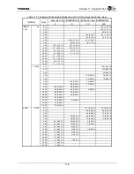
Table 11.3.1 shows example settings of divide values relative to representative baud rates.
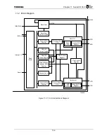
Figure 11.3.2 Baud Rate Generator and SIOCLK Generator
It is possible to correctly receive data if the error of the baud rate set by this controller is within 3.12
% of the target baud rate (communication baud rate).
Selector
Selector
Prescalar
Selector
SCLK
IMBUSCLKFF
Divider
Select CLK
SIBGR. BCLK
Baud Rate Generator
Select SIOCLK
SILCR. SCS [1]
T6
T4
T2
T0
SIOCLK
fc
Baud Rate
Divide value
SIBGR. BRD
Select SIOCLK
SILCR. SCS [0]
1/2
1/8
1/32
1/128
1/1
−
1/255
Summary of Contents for TMPR4925
Page 1: ...64 Bit TX System RISC TX49 Family TMPR4925 Rev 3 0 ...
Page 4: ......
Page 15: ...Handling Precautions ...
Page 16: ......
Page 18: ...1 Using Toshiba Semiconductors Safely 1 2 ...
Page 40: ...3 General Safety Precautions and Usage Considerations 3 18 ...
Page 42: ...4 Precautions and Usage Considerations 4 2 ...
Page 43: ...TMPR4925 ...
Page 44: ......
Page 54: ...Chapter 1 Features 1 8 ...
Page 58: ...Chapter 2 Block Diagram 2 4 ...
Page 88: ...Chapter 4 Address Mapping 4 12 ...
Page 226: ...Chapter 8 DMA Controller 8 58 ...
Page 260: ...Chapter 9 SDRAM Controller 9 34 ...
Page 480: ...Chapter 15 Interrupt Controller 15 32 ...
Page 554: ...Chapter 19 Real Time Clock RTC 19 8 ...
Page 555: ...Chapter 20 Removed 20 1 20 Removed ...
Page 556: ...Chapter 20 Removed 20 2 ...
Page 564: ...Chapter 21 Extended EJTAG Interface 21 8 ...
Page 580: ...Chapter 22 Electrical Characteristics 22 16 ...
Page 588: ...Chapter 24 Usage Notes 24 2 ...

