Chapter 22 Electrical Characteristics
22-10
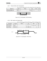
22.5.7 Interrupt Interface AC Characteristics
(Tc
= 0 ~ 70
°
C, V
CCIO
= 3.3 V
±
0.3 V, V
CCInt
= 1.5 V
±
0.1 V, V
SS
= 0 V)
Parameter Symbol Rating
Min.
Max.
Unit
INT Input pulse width time
t
PW_INT
1/2
×
t
MCP
×
1.1
⎯
ns
NMI Input pulse width time
t
PW_NMI
1/2
×
t
MCP
×
1.1
⎯
ns
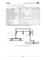
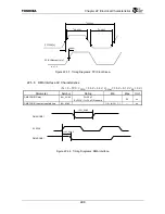
Figure 22.5.9 Timing Diagrams: INT/NMI Interface
22.5.8 SIO Interface AC Characteristics
(Tc
= 0 ~ 70
°
C, V
CCIO
= 3.3 V
±
0.3 V, V
CCInt
= 1.5 V
±
0.1 V, V
SS
= 0 V)
Parameter Symbol
Rating
Min.
Max. Unit
SCLK Cycle time
f
CYC_SCLK
t
MCP
×
1.1
⎯
ns
SCLK Frequency
f
SCLK
⎯
2
×
f
MCK
×
0.45
MHz
SCLK High time
t
HIGH_SCLK
1/2
×
t
MCP
×
1.1
⎯
ns
SCLK Low time
t
LOW_SCLK
1/2
×
t
MCP
×
1.1
⎯
ns
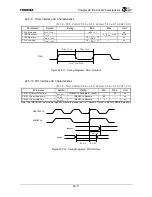
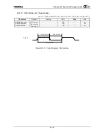
Figure 22.5.10 Timing Diagrams: SIO Interface
t
PW_INT
/t
PW_NMI
t
HIGH_SCLK
t
LOW_SCLK
SCLK
t
CYC_SCLK
/f
SCLK
Summary of Contents for TMPR4925
Page 1: ...64 Bit TX System RISC TX49 Family TMPR4925 Rev 3 0 ...
Page 4: ......
Page 15: ...Handling Precautions ...
Page 16: ......
Page 18: ...1 Using Toshiba Semiconductors Safely 1 2 ...
Page 40: ...3 General Safety Precautions and Usage Considerations 3 18 ...
Page 42: ...4 Precautions and Usage Considerations 4 2 ...
Page 43: ...TMPR4925 ...
Page 44: ......
Page 54: ...Chapter 1 Features 1 8 ...
Page 58: ...Chapter 2 Block Diagram 2 4 ...
Page 88: ...Chapter 4 Address Mapping 4 12 ...
Page 226: ...Chapter 8 DMA Controller 8 58 ...
Page 260: ...Chapter 9 SDRAM Controller 9 34 ...
Page 480: ...Chapter 15 Interrupt Controller 15 32 ...
Page 554: ...Chapter 19 Real Time Clock RTC 19 8 ...
Page 555: ...Chapter 20 Removed 20 1 20 Removed ...
Page 556: ...Chapter 20 Removed 20 2 ...
Page 564: ...Chapter 21 Extended EJTAG Interface 21 8 ...
Page 580: ...Chapter 22 Electrical Characteristics 22 16 ...
Page 588: ...Chapter 24 Usage Notes 24 2 ...


