


7- 1
Cleaning the Tracks
!
!
WARNING
If two people are doing this job make sure that the
person working the controls is a competent operator. If
the wrong control lever is moved, or if the controls are
moved violently, the other person could be killed or
injured.
If you will be working with another person, make sure
you both understand what the other will be doing. Learn
and use the recognised signalling procedures. Do not
rely on shouting - he will not hear you.
To clean the tracks you must turn them. When the tracks
are turning, keep clear of rotating parts.
Before starting this job, make sure that you have no
loose clothing
(cuffs, ties, etc)
which could get caught in
rotating parts.
Keep people not involved with the job well away!
8-3-3-1
1
Prepare the Machine
Park the machine on level ground. Open the bucket and
slew the boom until it is at 90° to the track. Lower the
bucket to the ground.
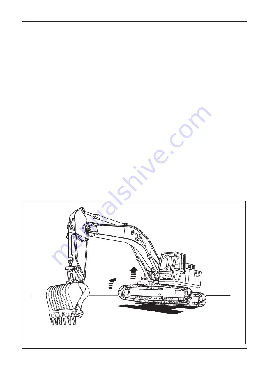
2
Raise the Track
Operate the boom and dipper controls so that the track
on the side nearest the bucket is lifted up clear of the
ground.
3
Rotate the Track
!
!
WARNING
Rotating the tracks off the ground may cause stones and
other debris to be thrown with considerable force. If you
are on the outside, keep well clear. Keep other people
well clear.
8-3-3-2
When it is safe to do so and you are
sure
that
everyone is clear of the machine, operate the controls to
rotate the track which is off the ground. Rotate it first one
way and then the other to shake off the mud. If necessary,
the person outside may use water to get the mud off.
4
Inspect the Track
When you have finished, inspect the track rollers,
sprockets and idler wheels for damage and oil leaks.
5
Lower the Track
Operate the boom and dipper controls to lower the
track to the ground.
6
Repeat for the Opposite Track
Slew the boom round to the other side and repeat
steps 2 to 5 inclusive for the other track.
Section 3
Routine Maintenance
9803/6410
Section 3
7 - 1
Issue 1
Tracks and Running Gear
Summary of Contents for JS130
Page 65: ...Section 3 Section 3 9803 6410 Issue 1 9 1 9 1 Routine Maintenance Component Location Diagram...
Page 118: ......
Page 119: ...3 1 Section C Electrics 9803 6410 Section C 3 1 Issue 1 Layout Operator s Cab...
Page 142: ...5 3 Section C Electrics 9803 6410 Section C 5 3 Issue 1 Pump Control FLOW CHART...
Page 207: ......
Page 209: ......
Page 210: ...3 4 Section E Hydraulics 9803 6410 Section E 3 4 Issue 2 Schematics Shuttle Block...
Page 532: ...Contents Page No Technical Data 1 1 i Engine 9803 6410 i Issue 1 Section K Section K...


