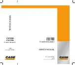
The coil of relay 1 is excited when the emergency stop
button is pressed when the key switch is
ON
(previous
section
A
), and the relay switch turns to the lower position.
Since the excitation voltage to relay 2 collapses, the relay
switch is returned to the upper position. The power supply
circuit of the motor is formed, rotates, turns to the stop
position, and the engine stops.
The motor switch is switched to upper position, and it stops.
4 - 7
Emergency stop button ON
Component Key (Pages 4-6 and 4-7)
C
Key switch
D
Emergency stop button
E
Fuse
F
Controller
G
Shut-down relay 1
H
Shut-down relay 2
J
Stop motor
K
Switch
L
Motor control - operating position
M
Motor control - stop position
N
To motor driver
P
Emergency stop signal
Section C
Electrics
9803/6410
Section C
4 - 7
Issue 1
Engine Control
C
C
G
G
J
J
K
K
D
D
E
E
F
F
N
N
P
P
H
H
J
J
M
M
M
M
Summary of Contents for JS130
Page 65: ...Section 3 Section 3 9803 6410 Issue 1 9 1 9 1 Routine Maintenance Component Location Diagram...
Page 118: ......
Page 119: ...3 1 Section C Electrics 9803 6410 Section C 3 1 Issue 1 Layout Operator s Cab...
Page 142: ...5 3 Section C Electrics 9803 6410 Section C 5 3 Issue 1 Pump Control FLOW CHART...
Page 207: ......
Page 209: ......
Page 210: ...3 4 Section E Hydraulics 9803 6410 Section E 3 4 Issue 2 Schematics Shuttle Block...
Page 532: ...Contents Page No Technical Data 1 1 i Engine 9803 6410 i Issue 1 Section K Section K...