PSoC CY8CTMG20x and CY8CTST200 TRM, Document No. 001-53603 Rev. *C
161
19. Programmable Timer
This chapter presents the Programmable Timer and its associated registers. For a complete table of the programmable timer
registers, refer to the
Summary Table of the System Resource Registers on page 106
. For a quick reference of all PSoC reg-
isters in address order, refer to the
Register Reference chapter on page 187
.
19.1
Architectural Description
The device has three programmable timers (TIMER0,
TIMER1, TIMER2). All three timers are individually con-
trolled. The programmable timers are 16-bit down counters
for the device. TIMER0 has a terminal count output. The tim-
ers have one configuration and two data registers associ-
ated with them. You start these timers by setting the START
bit in their configuration registers (PT0_CFG, PT1_CFG,
PT2_CFG). When started, the timers always start counting
down from the value loaded into their data registers
(PT*_DATA1, PT*_DATA0). The timers have a one-shot
mode, in which the timers complete one full count cycle and
stop. In one-shot mode the START bit in the configuration
register is cleared after completion of one full count cycle.
Setting the START bit restarts the timer.
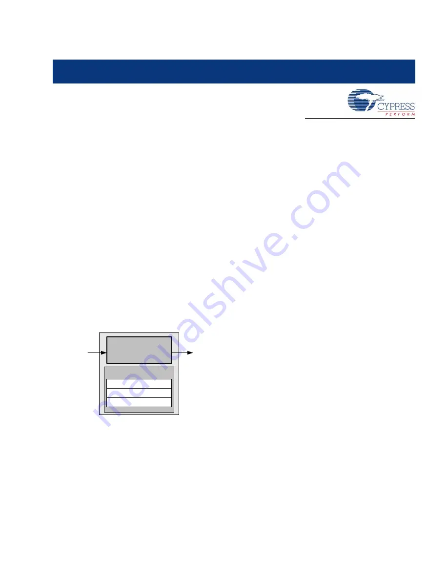
Figure 19-1. Programmable Timer Block Diagram
19.1.1
Operation
When started, the programmable timer loads the value con-
tained in its data registers and counts down to its terminal
count of zero. The timers output an active high terminal
count pulse for one clock cycle upon reaching the terminal
count. The low time of the terminal count pulse is equal to
the loaded decimal count value, multiplied by the clock
period (TC
pw
= COUNT VALUE
decimal
* CLK
period
). The
period of the terminal count output is the pulse width of the
terminal count, plus one clock period (TC
period
= TC
pw
+
CLK
period
). Refer to
Figure 19-2
and
.
Only TIMER0 outputs this terminal count output. TIMER1
and TIMER2 do not have a terminal count output.
The timers work on either the 32 kHz clock or CPU clock.
This clock selection is done using the CLKSEL bits in the
respective configuration registers (PT0_CFG, PT1_CFG,
PT2_CFG). Make clock selections before setting the START
bit so that the timing is not affected and clock frequency
does not change while the timer is running.
TIMER1 works on prescaled IMO clock (IMO-P) when the
CSD_MODE bit in the CS_CR0 (0,A0) register is set to ‘1’.
TIMER1 outputs the START signal, which used in the True-
Touch module during CSD mode. Refer to
for more details on TrueTouch CSD mode.
When CSD_MODE is set to ‘0‘, it works on either the 32 kHz
clock or CPU clock, depending on the CLKSEL bit setting.
Registers
32 kHz
Clock/ CPU
Clock
Programmable
Timer
CONFIGURATION[7:0]
DATA[7:0]
DATA[7:0]
Terminal
Count
Summary of Contents for PSoC CY8CTMG20 Series
Page 4: ...4 Contents Overview Feedback...
Page 26: ...26 PSoC CY8CTMG20x and CY8CTST200 TRM Document No 001 53603 Rev C Section B PSoC Core Feedback...
Page 82: ...82 PSoC CY8CTMG20x and CY8CTST200 TRM Document No 001 53603 Rev C Sleep and Watchdog Feedback...
Page 134: ...134 PSoC CY8CTMG20x and CY8CTST200 TRM Document No 001 53603 Rev C I2C Slave Feedback...
Page 142: ...142 PSoC CY8CTMG20x and CY8CTST200 TRM Document No 001 53603 Rev C System Resets Feedback...
Page 160: ...160 PSoC CY8CTMG20x and CY8CTST200 TRM Document No 001 53603 Rev C SPI Feedback...
Page 182: ...182 PSoC CY8CTMG20x and CY8CTST200 TRM Document No 001 53603 Rev C Full Speed USB Feedback...
Page 302: ...302 PSoC CY8CTMG20x and CY8CTST200 TRM Document No 001 53603 Rev C Glossary Feedback...


