X20 system modules • Analog output modules • X20AO4622
X20 system User's Manual 3.10
475
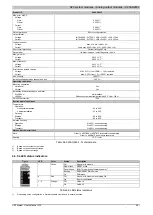
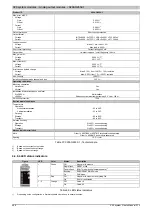
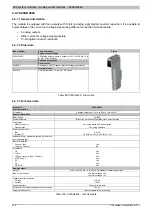
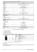
Product ID
X20AO4622
Max. error at 25°C
Voltage
Gain
0.080%
2)
Offset
0.050%
3)
Current
Gain
0.090%
2)
Offset
0.050%
3)
Output protection
Short circuit protection
Output format
Voltage
INT 0x8001 - 0x7FFF / 1 LSB = 0x0010 = 4.882 mV
Current
INT 0x8001 - 0x7FFF / 1 LSB = 0x0010 = 9.766 µA
Load per channel
Voltage
Max. ±10 mA, load ≥1 kΩ
Current
Load max. 600 Ω (Rev. ≥ J0); 500 Ω (Rev. < J0)
Short circuit protection
Current limiting ±40 mA
Output filter
1st-order low pass / cutoff frequency 10 kHz
Max. gain drift
Voltage
0.015 %/°C
2)
Current
0.020 %/°C
2)
Max. offset drift
Voltage
0.032 %/°C
3)
Current
0.032 %/°C
3)
Error caused by load change
Voltage
Max. 0.11%, from 10 MΩ → 1 kΩ, resistive
Current
Max. 0.50%, from 1 Ω → 600 Ω, resistive
Non-linearity
<0.005%
4)
Isolation voltage between channel and bus
500 V
eff
Operating conditions
Mounting orientation
Horizontal
Yes
Vertical
Yes
Installation at elevations above sea level
0 to 2000 m
No limitations
>2000 m
Reduction of ambient temperature by 0.5°C per 100 m
EN 60529 protection
IP20
Environmental conditions
Temperature
Operation
Horizontal installation
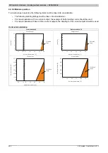
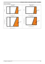
-25 to 60°C (Rev. ≥ J0); 0 to 55°C (Rev. < J0)
Vertical installation
-25 to 50°C (Rev. ≥ J0); 0 to 50°C (Rev. < J0)
Derating
See section "Module operation"
Storage
-40 to 85°C
Transport
-40 to 85°C
Relative humidity
Operation
5 to 95%, non-condensing
Storage
5 to 95%, non-condensing
Transport
5 to 95%, non-condensing
Mechanical characteristics
Note
Order 1x X20TB12 terminal block separately
Order 1x X20BM11 bus module separately
Spacing
12.5
+0.2
mm
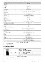
Table 100: X20AO4622 - Technical data
1)
4 to 20 mA: From upgrade version 1.0.2.0 or hardware revision "I0"
2)
Based on the current output value.
3)
Based on the entire output range.
4)
Based on the output range.
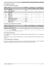
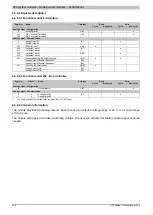
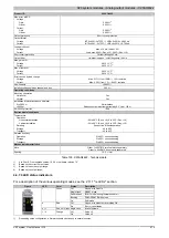
4.4.7.4 LED status indicators
For a description of the various operating modes, see the 2.11.1 "re LEDs" section.
Figure
LED
Color
Status
Description
Off
No power to module
Single flash
RESET mode
Double flash
BOOT mode (during firmware update)
1)
Blinking
PREOPERATIONAL mode
r
Green
On
RUN mode
Off
No power to module or everything OK
e
Red
On
Error or reset status
e + r
Red on / Green single flash
Invalid firmware
Off
Value = 0
1 - 4
Orange
On
Value ≠ 0
1)
Depending on the configuration, a firmware update can take up to several minutes.
Summary of Contents for X20 System
Page 2: ......

