Table of contents
X20 system User's Manual 3.10
37
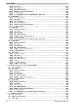
4.25.5.12 Overvoltage cutoff...................................................................................................................... 1963
4.25.5.13 Overtemperature cutoff (at 85°C).............................................................................................. 1963
4.25.5.14 Measurement of effective current.............................................................................................. 1963
4.25.5.15 Register description................................................................................................................... 1964
4.25.6 X20SM1426....................................................................................................................................... 1976
4.25.6.1 General information......................................................................................................................1976
4.25.6.2 Order data....................................................................................................................................1976
4.25.6.3 Technical data..............................................................................................................................1977
4.25.6.4 LED status indicators...................................................................................................................1978
4.25.6.5 Pinout........................................................................................................................................... 1978
4.25.6.6 Connection example.................................................................................................................... 1979
4.25.6.7 Connection options for digital inputs............................................................................................1979
4.25.6.8 Input circuit diagram.................................................................................................................... 1979
4.25.6.9 Output circuit diagram..................................................................................................................1980
4.25.6.10 Overvoltage cutoff...................................................................................................................... 1980
4.25.6.11 Overtemperature cutoff (at 85°C)...............................................................................................1980
4.25.6.12 Derating......................................................................................................................................1981
4.25.6.13 Register description................................................................................................................... 1983
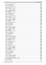
4.25.7 X20SM1436....................................................................................................................................... 2020
4.25.7.1 General information......................................................................................................................2020
4.25.7.2 Order data....................................................................................................................................2020
4.25.7.3 Technical data..............................................................................................................................2021
4.25.7.4 LED status indicators...................................................................................................................2022
4.25.7.5 Pinout........................................................................................................................................... 2022
4.25.7.6 Connection example.................................................................................................................... 2023
4.25.7.7 Connection options for digital inputs............................................................................................2023
4.25.7.8 Input circuit diagram.................................................................................................................... 2024
4.25.7.9 Output circuit diagram..................................................................................................................2024
4.25.7.10 Overvoltage motor cutoff............................................................................................................2024
4.25.7.11 Overtemperature cutoff (at 85°C)...............................................................................................2025
4.25.7.12 Power supply dimensioning....................................................................................................... 2025
4.25.7.13 Protection................................................................................................................................... 2026
4.25.7.14 Derating......................................................................................................................................2027
4.25.7.15 Register description................................................................................................................... 2029
4.26 Other functions........................................................................................................................................2066
4.26.1 Brief information.................................................................................................................................2066
4.26.2 X20CM4810....................................................................................................................................... 2067
4.26.2.1 Order data....................................................................................................................................2067
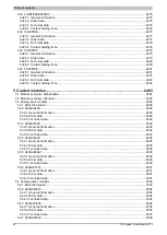
4.26.2.2 Technical data..............................................................................................................................2067
4.26.2.3 General information about the module........................................................................................ 2075
4.26.2.4 Condition monitoring / Oscillation analyses.................................................................................2077
4.26.2.5 Register description..................................................................................................................... 2147
4.26.2.6 FlatStream....................................................................................................................................2182
4.26.2.7 X20CM4810 on the fieldbus........................................................................................................ 2204
4.26.2.8 Accessories.................................................................................................................................. 2204
4.26.3 X20CM8281....................................................................................................................................... 2210
4.26.3.1 General information......................................................................................................................2210
4.26.3.2 Order data....................................................................................................................................2210
4.26.3.3 Technical data..............................................................................................................................2210
4.26.3.4 LED status indicators...................................................................................................................2213
4.26.3.5 Pinout........................................................................................................................................... 2213
4.26.3.6 Connection example.................................................................................................................... 2214
4.26.3.7 Input circuit diagram.................................................................................................................... 2214
4.26.3.8 Output circuit diagram..................................................................................................................2215
4.26.3.9 Switching inductive loads.............................................................................................................2215
4.26.3.10 Register description................................................................................................................... 2216
4.26.4 X20CM8323....................................................................................................................................... 2227
Summary of Contents for X20 System
Page 2: ......


