X20 system modules • Other functions • X20CM4810
X20 system User's Manual 3.10
2147
4.26.2.5 Register description
4.26.2.5.1 Function models
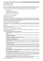
A function model specifies the storage model used, i.e. which registers are available for the application. Only these
registers are processed in the module during each cycle and transferred cyclically or acyclically via the bus.
The function model is used to determine the module's functionality. The following options are available:
•
Standard (SG4)
•
Fast master (SGC and bus coupler)
•
Slow master (SGC and bus coupler)
•
CANIOBusController (CANIO bus coupler)
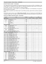
4.26.2.5.2 Function model 0 - Standard
Automation Runtime support
This is the default function model for the X20CM4810. The calculated module characteristic values are streamed
from the module via FlatStream every 300 ms and prepared for the user by Automation Runtime. If the streamed
data is not collected by the next transfer, the measured characteristic values are lost. For this reason, the maximum
cycle time must be observed for an error-free evaluation.
Analog inputs are provided as cyclic data points.
To help the user, all of the module's characteristic values – such as FlatStream handling for characteristic values,
unit scaling and so on – are prepared in this function model using Automation Runtime and then made available
to the user.
With this function model it is also possible to use an additional FlatStream to read data buffers (time signal and
FFT spectrum) from the module.
The AsVib function library is available for this application.
In this function model, the X20CM4810 can only be configured using the I/O configuration. Registers may not be
reconfigured asynchronously.
Features provided by Automation Runtime support:
•
This bit changes its value whenever new characteristic values are loaded from the
module.
•
Indicates whether a signal is pending on the input that is larger than the
configured AnalogInputScale.
Important!
This is always based on a 100 mV/g sensor.
•
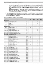
"OverflowCharacteristicValues01-04":
This register contains an overflow indicator bit for each charac-
teristic value of the respective channel.
•
: This register contains an overflow indicator bit for each frequency band.
•
: The module always expects a value in 0.01 Hz resolution on these data points. Au-
tomation Runtime support allows the the user to specify can state the current speed directly in Hz in the
"standard" function model.
•
: The X20CM4810 module expects a 100 mV/g sensor on the input by default.
When using other sensors, the sensor resolution can be specified in mV/g for each channel on these da-
ta points. All cyclical characteristic values are then automatically scaled to the correct sensor resolution
by Automation Runtime. If this parameter is changed, then the next measurement indicated by "DataTog-
gleBit01" is invalid.
•
The analog input is automatically scaled to the sensor resolution and with the defined
AnalogInputScale. It is then made available to the user in mg. This scaling does not apply to the "Crest
factor" since it is a non-dimensional value.
•
Characteristic values and frequency bands:
All characteristic values and frequency bands calculated
by the X20CM4810 are flat and can be connected directly in the I/O mapping. They are already scaled to
the correct sensor resolution and will be displayed in mg or mm/s or as non-dimensional values (kurtosis,
crest factor, skewness and Vdi3832) depending on the characteristic value.
•
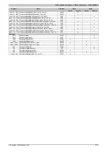
Additional characteristic values:
In addition to the characteristic values calculated by the module, the
following characteristic values are also provided automatically via Automation Runtime:
Summary of Contents for X20 System
Page 2: ......

