X20 system modules • Motor controllers • X20SM1436
2052
X20 system User's Manual 3.10
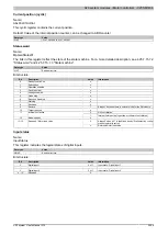
Limit switch configuration
Name:
LimitSwitchConfig01
This register can be used to configure the behavior of the limit switch.
Data type
Value
USINT
See bit structure.
Bit structure:
Bit
Description
Value
Information
00
Off
01
Active if low
10
Reserved
0 - 1
Negative limit switch
11
Active if high
00
Off
01
Active if low
10
Reserved
2 - 3
Positive limit switch
11
Active if high
4 - 6
Reserved
0
0
Off (default)
7
Direction monitoring
1
On
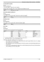
Negative/positive limit switch
When one of the limit switches is reached, a warning is triggered and the speed is decelerated to 0. The "Device
Control State Machine" state is not changed. This keeps current flowing to the motor.
The error that occurred can be read from the Error code register. Normal operation can be resumed by acknowl-
edging the warning. This will not restrict motor movement to a specific direction and the limit switch will not be
triggered until the next active edge.
Exceeding the limit switch while braking
The limit switches are not linked with the corresponding direction of movement. If the limit switch is exceeded,
another error will be triggered when reversing after acknowledging the initial error.
Direction monitoring
If this function is enabled, then the two limit switches will be linked with the respective direction of movement. This
means that the negative limit switch is only triggered in the negative direction and the positive limit switch only in
the positive direction of movement (specified direction).
This prevents specifying a movement in the wrong direction when direction monitoring is enabled and limit switches
are active.
Warning!
If the motor is wired incorrectly with this configuration (wrong direction of movement), then the limit
switch will not be triggered and the actual correct direction of movement will be denied. This will also
be the case when the limit switch connections are reversed.
Summary of Contents for X20 System
Page 2: ......


