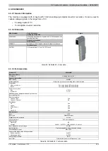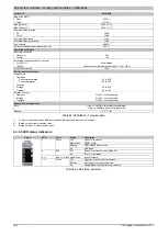
X20 system modules • Analog input modules • X20AI2622
256
X20 system User's Manual 3.10
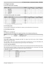
4.3.8.8.6 Configuring the input filter
Name:
ConfigOutput01
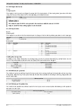
This register is used to define the filter level and input ramp limitation of the input filter.
Data type
Value
USINT
See bit structure.
Bit structure:
Bit
Description
Value
Information
000
Filter switched off
001
Filter level 2
010
Filter level 4
011
Filter level 8
100
Filter level 16
101
Filter level 32
110
Filter level 64
0 - 2
Defines the filter level
111
Filter level 128
3
Reserved
0
000
The input value is used without limitation
001
Limit value = 0x3FFF (16383)
010
Limit value = 0x1FFF (8191)
011
Limit value = 0x0FFF (4095)
100
Limit value = 0x07FF (2047)
101
Limit value = 0x03FF (1023)
110
Limit value = 0x01FF (511)
4 - 6
Defines the input ramp limitation
111
Limit value = 0x00FF (255)
7
Reserved
0
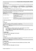
4.3.8.8.7 Channel type
Name:
ConfigOutput02
This register can be used to define the type and range of signal measurement.
Each channel is capable of handling either current or voltage signals. This differentiation is made using multiple
connection terminal points and an integrated switch in the module. The switch is automatically activated by the
module depending on the specified configuration. The following input signals can be set:
•
±10 V voltage signal (default)
•
0 to 20 mA current signal
•
4 to 20 mA current signal
Data type
Value
USINT
See bit structure.
Bit structure:
Bit
Description
Value
Information
0
Voltage signal
0
Channel 1
1
Current signal, measurement range corresponding to bit 4
0
Voltage signal
1
Channel 2
1
Current signal, measurement range corresponding to bit 5
2 - 3
0
0
0 to 20 mA current signal
4
Channel 1: Current measurement range
1
4 to 20 mA current signal
0
0 to 20 mA current signal
5
Channel 2: Current measurement range
1
4 to 20 mA current signal
6 - 7
0
Summary of Contents for X20 System
Page 2: ......


