X20 system modules • Other functions • X20CM8281
2212
X20 system User's Manual 3.10
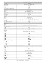
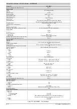
Product ID
X20CM8281
Isolation voltage between channel and bus
500 V
eff
Digital outputs
Design
FET positive switching
Quantity
2
Nominal voltage
24 VDC
Switching voltage
24 VDC -15% / +20%
Nominal output current
0.5 A
Total nominal current
1.0 A
Connection type
1-wire connections
Output circuit
Source
Output protection
Thermal cutoff if overcurrent or short circuit occurs, integrat-
ed protection for switching inductances, reverse polarity protection
Diagnostic status
Output monitoring with 10 ms delay
Leakage current when switched off
5 µA
R
DS(on)
105 mΩ
Peak short circuit current
<14 A
Switching on after overload or short circuit cutoff
Ca. 10 ms (depends on the module temperature)
Switching delay
0 -> 1
<250 µs
1 -> 0
<270 µs
Switching frequency
Resistive load
Max. 100 Hz
Inductive load
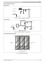
See section "Switching inductive loads"
Braking voltage when switching off inductive loads
Typ. 50 VDC
Isolation voltage between channel and bus
500 V
eff
Analog outputs
Quantity
1
Output
±10 V or 0 to 20 mA, via different terminal connections
Digital converter resolution
12-bit
Conversion time
300 µs, conversion runs asynchronously to the X2X Link cycle
Settling time for output changes over entire range
1 ms
Power on/off behavior
Internal enable relay for booting and errors
Max. error at 25°C
Voltage
Gain
0.040%
4)
Offset
0.0225%
5)
Current
Gain
0.05%
4)
Offset
0.125%
5)
Output protection
Short circuit protection
Output format
Voltage
INT 0x8001 - 0x7FFF / 1 LSB = 0x0010 = 4.882 mV
Current
INT 0x8001 - 0x7FFF / 1 LSB = 0x0010 = 9.766 µA
Load per channel
Voltage
Max. ±10 mA, load ≥ 1 kΩ
Current
Max. load is 400 Ω
Max. gain drift
Voltage
0.012 %/°C
4)
Current
0.014 %/°C
4)
Max. offset drift
Voltage
0.0075 %/°C
5)
Current
0.03 %/°C
5)
Error caused by load change
Voltage
Max. 0.02%, from 10 MΩ → 1 kΩ, resistive
Current
Max. 0.5%, from 1 Ω → 400 Ω, resistive
Non-linearity
<0.1%
6)
Isolation voltage between channel and bus
500 V
eff
Operating conditions
Mounting orientation
Horizontal
Yes
Vertical
Yes
Installation at altitudes above sea level
0 to 2000 m
No limitations
>2000 m
Reduction of ambient temperature by 0.5°C per 100 m
EN 60529 protection
IP20
Environmental conditions
Temperature
Operation
Horizontal installation
-25 to 60°C
Vertical installation
-25 to 50°C
Derating
When operated at temperatures above 55°C, the power consumption of
the modules to the left and right of this module must not exceed 1.15 W
Storage
-40 to 85°C
Transport
-40 to 85°C
Table 775: X20CM8281 - Technical data
Summary of Contents for X20 System
Page 2: ......


