X20 system modules • Digital signal processing modules • X20CM1201
X20 system User's Manual 3.10
1313
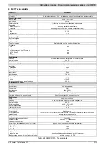
4.16.2.3 Technical data
Product ID
X20CM1201
Short description
I/O module
1 AB incremental encoder, 24 V, 4 digital inputs, 4 channels configurable as inputs or outputs
General information
Input voltage
24 VDC -15% / +20%
B&R ID code
0x21EF
Status indicators
I/O function per channel, operating state, module status
Diagnostics
Module run/error
Yes, using status LED and software
Outputs
Yes, using the status LED and software (output error status)
Power consumption
Bus
0.01 W
Internal I/O
1.5 W
Additional power dissipation caused by the actua-
tors (resistive) [W]
-
Electrical isolation
Channel - Bus
Yes
Channel - Channel
No
Type of signal lines
Shielded cables must be used for all signal lines.
Certification
CE
Yes
cULus
Yes
cCSAus HazLoc Class 1 Division 2
Yes
ATEX Zone 2
Yes
KC
Yes
GOST-R
Yes
Digital inputs
Quantity
4 + 4 additional channels, configurable as inputs or outputs
Nominal voltage
24 VDC
Input voltage
24 VDC -15% / +20%
Input current at 24 VDC
Approx. 1.3 mA
Input filter
Hardware
≤2 μs
Software
-
Connection type
1-wire connections
Input circuit
Sink
Input resistance
18.4 kΩ
Switching threshold
Low
<5 VDC
High
>15 VDC
Isolation voltage between channel and bus
500 V
eff
AB incremental encoder
Quantity
1
Encoder inputs
24 V, asymmetrical
Counter size
32-bit
Input frequency
Max. 100 kHz
Evaluation
4x
Encoder supply
Module-internal, max. 600 mA
Overload behavior of the encoder supply
Short circuit protection, overload protection
Digital outputs
Design
Push / Pull / Push-Pull
Quantity
Up to 4, configurable as inputs or outputs using software
Nominal voltage
24 VDC
Switching voltage
24 VDC -15% / +20%
Nominal output current
0.1 A
Total nominal current
0.4 A
Connection type
1-wire connections
Output circuit
Sink or source
Output protection
Thermal cutoff if overcurrent or short circuit occurs, integrated protection for switching inductances
Actuator supply
Module-internal, max. 600 mA
Diagnostic status
Output monitoring
Leakage current when switched off
Max. 25 µA
Residual voltage
<0.9 V at 0.1 A rated current
Peak short circuit current
<10 A
Switching on after overload or short circuit cutoff
Approx. 10 ms (depends on the module temperature)
Switching delay
0 -> 1
<2 µs
1 -> 0
<2 µs
Switching frequency
Resistive load
Max. 24 kHz
Inductive load
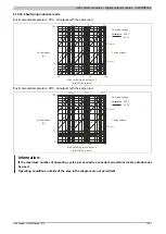
See section "Switching inductive loads" (at 90% duty cycle).
Braking voltage when switching off inductive loads
Switching v 0.6 VDC
Table 424: X20CM1201 - Technical data
Summary of Contents for X20 System
Page 2: ......

