X20 system modules • Power supply modules • X20PS2110
2338
X20 system User's Manual 3.10
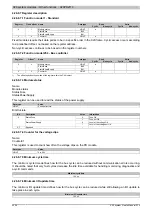
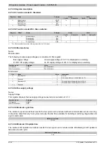
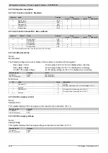
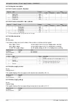
4.27.3.8 Register description
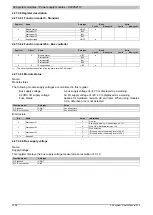
4.27.3.8.1 Function model 0 - Standard
Read
Write
Register
Name
Data type
Cyclic
Non-cyclic
Cyclic
Non-cyclic
USINT
StatusInput01
Bit 0
StatusInput02
Bit 1
0
StatusInput03
Bit 2
●
4
USINT
●
4.27.3.8.2 Function model 254 - Bus controller
Read
Write
Register
Offset
1)
Name
Data type
Cyclic
Non-cyclic
Cyclic
Non-cyclic
UINT
StatusInput01
Bit 0
StatusInput02
Bit 1
0
0
StatusInput03
Bit 2
●
4
4
UINT
●
1)
The offset specifies the position of the register within the CAN object.
4.27.3.8.3 Module status
Name:
Module status
The following module supply voltages are monitored in this register:
Bus supply voltage:
A bus supply voltage of <4.7V is displayed as a warning.
24 VDC I/O supply voltage:
An I/O supply voltage of <20.4 V is displayed as a warning.
Fuse status:
Applies for hardware revision C0 and later. When using modules
C0, a defective fuse is not detected.
Function model
Data type
Value
0 - Standard
USINT
See bit structure.
254 - Bus controller
UINT
See bit structure.
Bit structure:
Bit
Name
Value
Information
0
No error
0
StatusInput01
1
Bus supply warning - Undervoltage (<4.7V)
0
Fuse OK or hardware revision <C0
1
StatusInput02
1
Fuse defective
0
I/O supply above the warning level of 20.4 V
2
StatusInput03
1
I/O supply below the warning level of 20.4 V
3 - x
Reserved
0
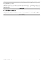
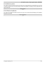
4.27.3.8.4 Bus supply voltage
Name:
SupplyVoltage
This register displays the bus supply voltage measured at a resolution of 0.1 V.
Function model
Data type
0 - Standard
USINT
254 - Bus controller
UINT
Summary of Contents for X20 System
Page 2: ......

