X20 system modules • X20 interface module communication • X20IF10E3-1
X20 system User's Manual 3.10
1851
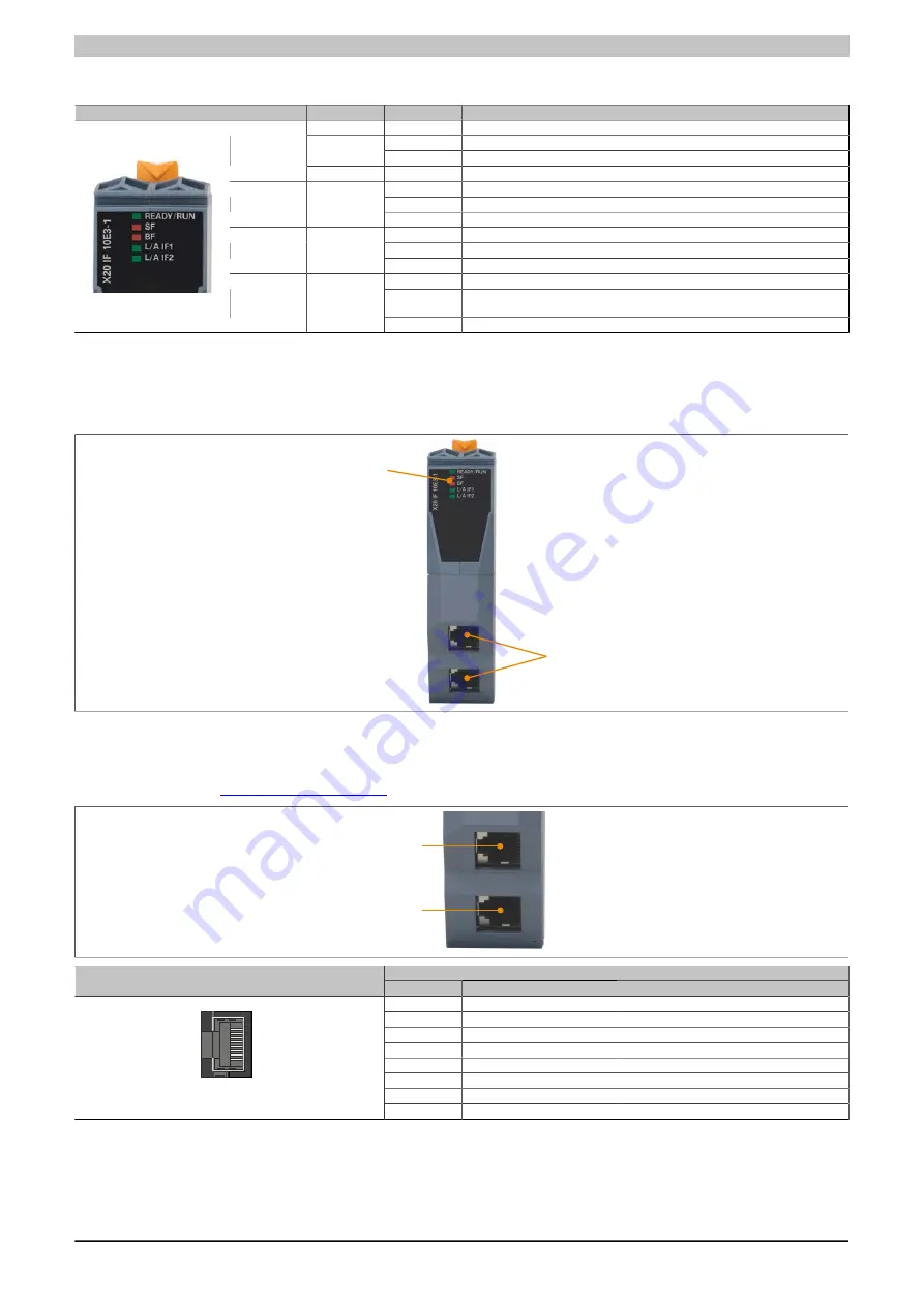
4.23.22.4 LED status indicators
Figure
LED
Color
Status
Description
Green/red
Off
No power to module
Blinking
Boot error
Red
On
Communication on the PCI bus has not yet been started
READY/RUN
Green
On
PCI bus communication in progress
Off
No error
Cyc. Blinking
1)
DCP signal service triggered via bus
SF
Red
On
System errors
Off
No error
Blinking
No data exchange
BF
Red
On
No configuration or physical connection error
Off
No link to remote station
Flickering
A link to the remote station has been established. The LED blinks when Ethernet
activity is taking place on the bus.
L/A IF1/IF2
Green
On
A link to the remote station has been established.
Table 638: LED status indicators
1)
Blinks cyclically at 2 Hz, duration 3 s.
4.23.22.5 Operating and connection elements
LED status indicators
Profinet RT connection with
2x RJ45 ports for easy wiring
4.23.22.6 Ethernet interface
Information about cabling X20 modules with an Ethernet interface can be found in the module's download section
P1 (IF1)
P2 (IF2)
P1
P2
Pinout
Interface
Pin
Ethernet
1
RXD
Receive data
2
RXD\
Receive data\
3
TXD
Transmit data
4
Termination
5
Termination
6
TXD\
Transmit data\
7
Termination
1
Shielded RJ45
8
Termination
Table 639: Pinout
Summary of Contents for X20 System
Page 2: ......


