X20 system modules • X20 interface module communication • X20IF1051-1
1786
X20 system User's Manual 3.10
4.23.6.6 DeviceNet interface
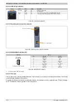
The interface is a 5-pin multipoint plug. The 0TB2105 terminal block must be ordered separately.
Interface
Pinout
Terminal
DeviceNet
1
CAN⊥
(V-)
CAN ground
2
CAN_L
CAN low
3
SHLD
Shield
4
CAN_H
CAN high
5
V+
Supply voltage
1)
1
5
5-pin male multipoint connector
Table 561: Pinout
1)
A 24 V supply voltage can be connected here for non-B&R products. The supply is only passed through. B&R modules neither provide nor require this
voltage supply.
4.23.6.7 Terminating resistor
On
Off
Terminating resistor switch
A terminating resistor is integrated in the interface module. It can be turned on and off with a switch on the bottom
of the housing. An active terminating resistor is indicated by the "TERM" LED.
4.23.6.8 Use with POWERLINK bus controllers
When this module is connected to the expandable POWERLINK bus controller, the amount of cyclic data is limited
by the POWERLINK frame to 1488 bytes in each direction (input and output).
When using multiple IF10xx-1 interfaces or other X2X modules with a POWERLINK bus controller, the 1488 bytes
are divided between all connected modules.
4.23.6.8.1 Operating netX modules with the X20BC1083 bus controller
The following must be taken into account to operate netX modules with the bus controller without problems:
•
A minimum revision ≥E0 is required for the bus controller.
•
NetX modules can only be operated with POWERLINK V2. V1 is not permitted.
4.23.6.9 Firmware
This module comes with preinstalled firmware. The firmware is a component of Automation Studio. The module
is automatically updated to this version.
To update the firmware included in Automation Studio, the hardware must be upgraded (see "Project manage-
ment" / "Automation Studio upgrade" in the help system).
Summary of Contents for X20 System
Page 2: ......


