X20 system modules • Motor controllers • X20SM1426
X20 system User's Manual 3.10
2017
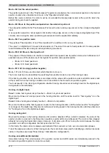
4.25.6.13.7.2 Status word
The individual bits of this register and its states depend on the current state of the state machine:
Status
R
es
er
vi
er
t /
M
ot
or
Lo
ad
B
it
2
1)
R
es
er
vi
er
t /
M
ot
or
Lo
ad
B
it
1
1)
R
es
er
vi
er
t /
M
ot
or
Lo
ad
B
it
0
1)
R
es
er
ve
d
In
t.
lim
it
ac
tiv
e
Ta
rg
et
re
ac
he
d
R
em
ot
e
R
es
er
ve
d
W
ar
ni
ng
Sw
itc
h
on
d
is
ab
le
d
Q
ui
ck
s
to
p
Vo
lta
ge
e
na
bl
ed
Fa
ul
t
O
pe
ra
tio
n
en
ab
le
d
Sw
itc
he
d
on
R
ea
dy
to
s
w
itc
h
on
Bit
15
14
13
12
11
10
9
8
7
6
5
4
3
2
1
0
Not ready to switch on
x
x
x
x
x
x
1
0
x
0
x
0
0
0
0
0
Switch on disabled
x
x
x
x
x
x
1
0
x
1
x
0
0
0
0
0
Ready to switch on
x
x
x
x
x
x
1
0
x
0
1
0
0
0
0
1
Switched on
x
x
x
x
x
x
1
0
x
0
1
1
0
0
1
1
Operation enable
x
x
x
x
x
x
1
0
x
0
1
1
0
1
1
1
Quick stop active
x
x
x
x
x
x
1
0
x
0
0
1
0
1
1
1
Fault reaction active
x
x
x
x
x
x
1
0
x
0
x
0
1
1
1
1
Fault
x
x
x
x
x
x
1
0
x
0
x
0
1
0
0
0
1)
If bit 7 is set to 1 in the Mixed decay / Stall detection register, then the motor load value is returned in bits 13-15 of the status word. Otherwise these bits
are always 0.
Information about the status word:
Bits 0,1,2,3,5 and 6
(light gray in the previous table)
These bits are set according to the current state of the "State machine".
Voltage enabled
Becomes 1 as soon as the motor is powered
Warning
Becomes 1 if a warning is detected ("Overcurrent", "Undercurrent"). The type of warning is indicated in the "Error
code" register. The highest priority error / warning is shown in each case, with the priority corresponding to the
order in the respective table. Warnings can be reset with a rising edge on the "Warning reset" bit in the control
word.
Remote
Always 1 since there is no local mode on the SM module
If Halt = 0
If Halt = 1
Target reached
1)
, depending on bit 8 (Halt) in
In modes 1, -123, -124, -125 and -126 (absolute po-
sitioning):
0... Positioning begins
1... Target has been reached
In mode 2 (constant speed):
0... Motor accelerates/brakes
1... Speed setpoint reached
In modes -127 and -128 (homing):
0... Homing started
1... Homing ended
In mode -122 (set actual position):
The bit briefly becomes 0 and immediately becomes 1
again as soon as the position is set.
In all modes:
0... Axis decelerating
1... Axis speed = 0
Internal limit active
0 ... No limit violation
1 ... Internal limit is active (upper/lower software limit violated)
Table 710: Information about the status word
1)
If Halt has not been activated in the "General configuration" register, then "Target Reached" behaves the same as when Halt = 0.
4.25.6.13.7.3 State machine
The motor is controlled according to the state machine illustrated below. After the module is started, the state
machine automatically changes to the state "
Not ready to switch on
". The application then operates the state
machine by writing commands to the "Control word".
The state machine successively reaches the states "
Ready to switch on
", "
Switched on
" and "
Operation enable
"
by writing the consecutive commands "
Shutdown
", "
Switch on
" and "
Enable operation
".
Information:
Motor movements are not performed until the "
Operation enable
" state, according to the setting in the
Summary of Contents for X20 System
Page 2: ......

