X20 system modules • Other functions • X20CM4810
2110
X20 system User's Manual 3.10
The following signals can be selected for each channel:
•
Raw acceleration signal
•
Raw velocity signal. Equal to 0 if the speed calculation is disabled.
•
Enveloped acceleration signal
•
Enveloped velocity signal. Equal to 0 if the speed calculation is disabled.
The harmonic frequencies (whole number multiples) of the window can also be included in the calculation. Here,
the width of the window is simply retained and the mean frequency of the window is multiplied (by *1, *2, *3, etc.)
until the maximum frequency of the set signal and channel is reached.
Useful information
If a fixed frequency band is needed in which the minimum frequency ("FrequencyBandXXLowerFrequency") and
maximum frequency ("FrequencyBandXXUpperFrequency") must be set with a higher precision than 0.25 Hz, then
a speed-dependent frequency band with a fixed speed can be used.
Noise
In this configuration, the noise from a quadrant of the respective signal on the selected channel that is within the
frequency band is calculated.
To do this, the configured maximum frequency of the signal on the selected channel is divided by 4. This results
in 4 quadrants. A configuration can then be used to select one of the 4 quadrants in which the noise should be
determined.
The following signals can be selected for each channel:
•
Raw acceleration signal
•
Raw velocity signal. Equal to 0 if the speed calculation is disabled.
•
Enveloped acceleration signal
•
Enveloped velocity signal. Equal to 0 if the speed calculation is disabled.
This configuration allows slippage to be effectively measured, for example. The higher the friction, the more noise
that is created.
Configuration options
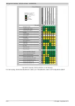
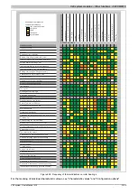
Each of the 32 frequency bands can be configured to one of the following characteristic values.
FrequencyBandRmsVelEnvelope
The RMS value formed from the envelope signal of the oscillation acceleration in a freely selectable frequency
range.
This frequency band is only calculated if the EnableVelocityCalculation bit (configured in the "SensorConfig01"
register) of the respective channel is set; otherwise, 0 is output.
Example:
Defects in toothed belts
FrequencyBandRmsAccEnvelope
The RMS value formed from the envelope signal of the oscillation acceleration in a freely selectable frequency
range.
Example:
Gear damage
FrequencyBandNoiseAccRaw
The noise value formed from the envelope signal of the oscillation acceleration in a freely selectable frequency
range.
Example:
Imbalance of toothed belts
Summary of Contents for X20 System
Page 2: ......


