X20 system modules • Digital output modules • X20DOF322
1308
X20 system User's Manual 3.10
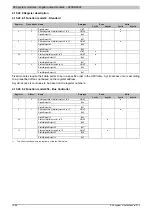
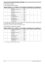
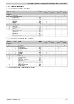
4.15.30.9 Register description
4.15.30.9.1 Function model 0 - Standard
Read
Write
Register
Fixed offset
Name
Data type
Cyclic
Acyclic
Cyclic
Acyclic
0
UINT
Switching state of digital outputs 1 to 8
USINT
DigitalOutput01
Bit 0
...
...
2
0
DigitalOutput08
Bit 7
Switching state of digital outputs 9 to 16
USINT
DigitalOutput09
Bit 0
...
...
3
1
DigitalOutput16
Bit 7
●
2
UINT
Status of digital outputs 1 to 8
USINT
StatusDigitalOutput01
Bit 0
...
...
30
2
StatusDigitalOutput08
Bit 7
Status of digital outputs 9 to 16
USINT
StatusDigitalOutput09
Bit 0
...
...
31
3
StatusDigitalOutput16
Bit 7
●
Fixed modules require their data points to be in a specific order in the X2X frame. Cyclic access occurs according
to a predefined offset, not based on the register address.
Acyclic access is continues to be based on the register numbers.
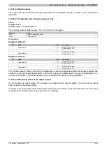
4.15.30.9.2 Function model 254 - Bus Controller
Read
Write
Register
Offset
1)
Name
Data type
Cyclic
Acyclic
Cyclic
Acyclic
Switching state of digital outputs 1 to 8
USINT
DigitalOutput01
Bit 0
...
...
2
0
DigitalOutput08
Bit 7
Switching state of digital outputs 9 to 16
USINT
DigitalOutput09
Bit 0
...
...
3
1
DigitalOutput16
Bit 7
●
Status of digital outputs 1 to 8
USINT
StatusDigitalOutput01
Bit 0
...
...
30
-
StatusDigitalOutput08
Bit 7
Status of digital outputs 9 to 16
USINT
StatusDigitalOutput09
Bit 0
...
...
31
-
StatusDigitalOutput16
Bit 7
●
1)
The offset specifies where the register is within the CAN object.
Summary of Contents for X20 System
Page 2: ......

