X20 system modules • Counter modules • X20DC2190
792
X20 system User's Manual 3.10
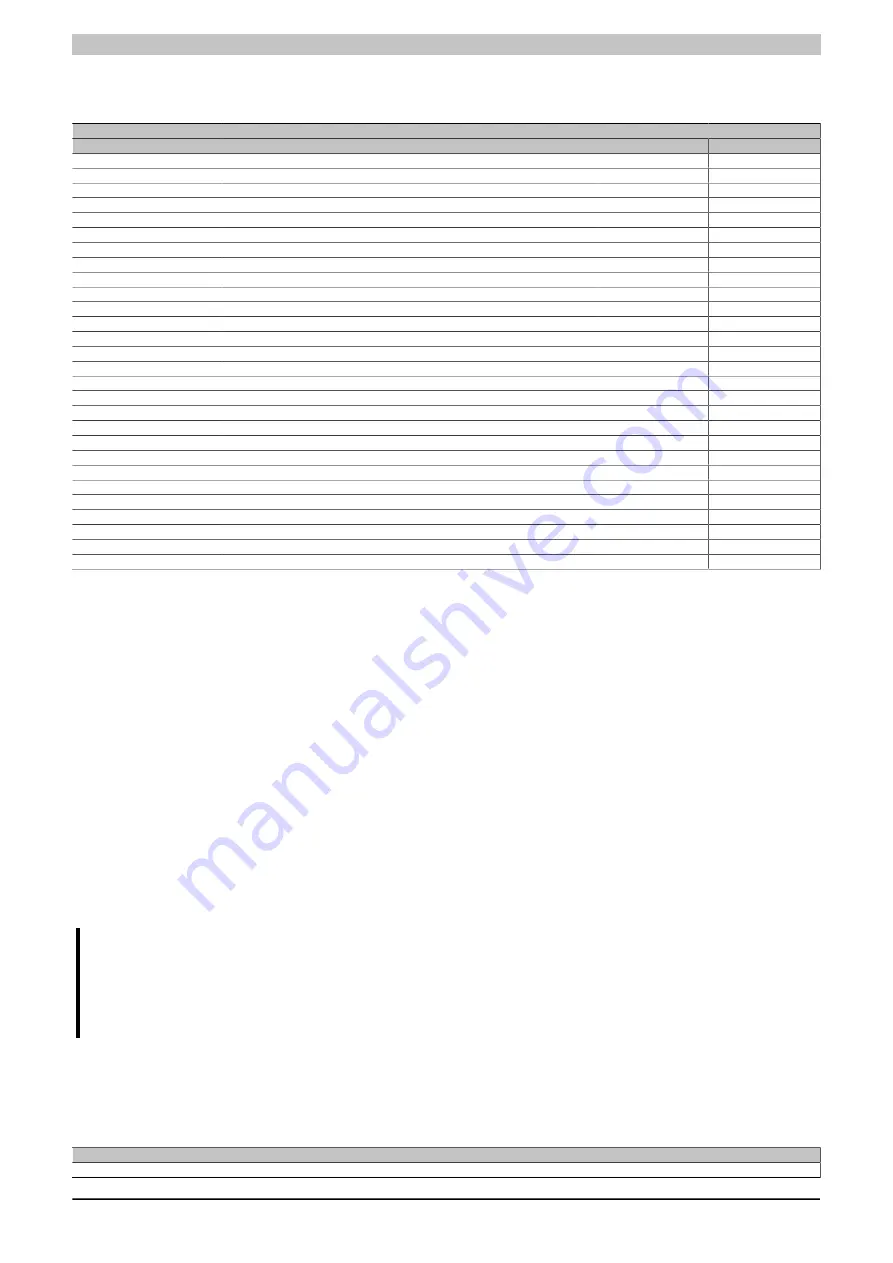
4.11.13.7.17.1 Parameter overview
The following parameters are stored in the status registers:
Register
Description
Supported by the protocol
DP/IP
EP
StatusInput09
Rod length 1 [mm]
●
●
StatusInput10
Rod length 2 [mm]
●
●
StatusInput11
Ultrasonic speed 1
●
●
StatusInput12
Ultrasonic speed 2
●
●
StatusInput13
Rod 1: Zero point offset [µm]
●
●
StatusInput14
Rod 2: Zero point offset [µm]
●
●
StatusInput15
Rod 1: Vendor ID (see transducer rod data sheet)
●
●
StatusInput16
Rod 2: Vendor ID (see transducer rod data sheet)
●
●
StatusInput17
Rod 1: Serial number (Hex coded)
●
●
StatusInput18
Rod 2: Serial number (Hex coded)
●
●
StatusInput19
Rod 1: Type ID 1 (MSB = letter 1)
●
0x0000
StatusInput20
Rod 1: Type ID 2 (MSB = letter 5)
●
0x0000
StatusInput21
Rod 1: Type ID 3 (MSB = letter 9)
●
0x0000
StatusInput22
Rod 1: Type ID 4 (MSB = letter 13)
●
0x0000
StatusInput23
Rod 1: Type ID 5 (MSB = letter 17)
●
0x0000
StatusInput24
Rod 1: Type ID 6 (MSB = letter 21)
●
0x0000
StatusInput25
Rod 2: Type ID 1 (MSB = letter 1)
●
0x0000
StatusInput26
Rod 2: Type ID 2 (MSB = letter 5)
●
0x0000
StatusInput27
Rod 2: Type ID 3 (MSB = letter 9)
●
0x0000
StatusInput28
Rod 2: Type ID 4 (MSB = letter 13)
●
0x0000
StatusInput29
Rod 2: Type ID 5 (MSB = letter 17)
●
0x0000
StatusInput30
Rod 2: Type ID 6 (MSB = letter 21)
●
0x0000
StatusInput31
Rod 1: Serial number ASCII 1 (MSB = letter 1)
●
0x0000
StatusInput32
Rod 1: Serial number ASCII 2 (MSB = letter 5)
●
0x0000
StatusInput33
Rod 1: Serial number ASCII 3 (MSB = letter 9)
●
0x0000
StatusInput34
Rod 2: Serial number ASCII 1 (MSB = letter 1)
●
0x0000
StatusInput35
Rod 2: Serial number ASCII 2 (MSB = letter 5)
●
0x0000
StatusInput36
Rod 2: Serial number ASCII 3 (MSB = letter 9)
●
0x0000
4.11.13.7.17.2 DPI/IP protocol (BALLUFF) / EP protocol (MTS)
Requirements for a successful upload of the transducer rod parameters to the module:
1. Selection of the communication protocol (DPI/IP or EP). See section . 4.11.13.7.11 "Channel configuration"
2. Transducer rod must support the respective protocol.
3. If the transducer rod does not support the selected protocol, the module will detect this after a timeout of
approx. 300 ms and will treat the rod as a "normal" transducer rod.
After the module is started or after a transducer rod is connected, the parameter upload should be complete within
200 to 400 ms.
A communication error causes the data upload to cancel. A new upload attempt can be initiated by the user by
deactivating and reactivating the communication protocol using asynchronous access.
All rod parameters can be read to the controller using asynchronous access. The read parameters "rod length"
and "ultrasonic speed" are
NOT
automatically uploaded to the module.
It is left up to the application whether the upload values for rod length 1 and rod length 2 or for ultrasonic speed 1
and ultrasonic speed 2 are uploaded.
Information:
Keep in mind that no position measurements can be performed on a rod while parameters are being
uploaded. The module freezes all existing position/speed data for all magnets on the rod while the
parameters are uploading. Parameters should therefore only be uploaded with the machine stopped,
and this should be ensured by the application.
4.11.13.7.18 Minimum cycle time
The minimum cycle time defines how far the bus cycle can be reduced without communication errors occurring.
It should be noted that very fast cycles decrease the idle time available for handling monitoring, diagnostics and
acyclic commands.
Minimum cycle time
250 µs
Summary of Contents for X20 System
Page 2: ......


