X20 system modules • Analog output modules • X20AO2632-1
X20 system User's Manual 3.10
473
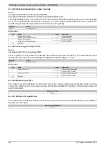
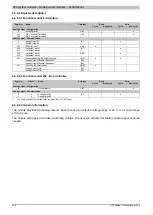
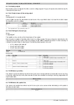
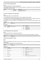
4.4.6.8.5.4 Enabling/disabling the output channels
Name:
AnalogOutput01Enable to AnalogOutput02Enable
AnalogOutput01EnableReadback to AnalogOutput02EnableReadback
The "OutputEnable" byte is only needed for the channels with activated time-based monitoring. The individual bits
are used to enable/disable the respective channels. To receive reliable feedback about the current state of the
module, the byte was also implemented so that it can be read cyclically.
Data type
Value
USINT
See bit structure
Bit structure:
Bit
Name
Value
Information
0
Output deactivated
0
AnalogOutput01Enable
AnalogOutput01EnableReadback
1
Output activated
0
Output deactivated
1
AnalogOutput02Enable
AnalogOutput02EnableReadback
1
Output activated
2 - 7
Reserved
0
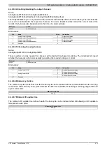
4.4.6.8.5.5 Checking the output values
Name:
AnalogOutput01OK to AnalogOutput02OK
These registers are only needed for channels with activated time-based monitoring. The individual bits report
whether the respective channel is actually generating the required voltage or current.
Data type
Value
USINT
See bit structure
Bit structure:
Bit
Name
Value
Information
0
Electrical signal deactivated
0
AnalogOutput01OK
1
Electrical signal activated
0
Electrical signal deactivated
1
AnalogOutput02OK
1
Electrical signal activated
2 - 7
Reserved
0
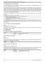
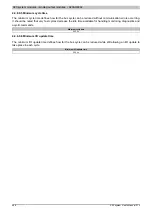
4.4.6.8.6 Minimum cycle time
The minimum cycle time defines how far the bus cycle can be reduced without communication errors occurring.
It should be noted that very fast cycles decrease the idle time available for handling monitoring, diagnostics and
acyclic commands.
Minimum cycle time
200 µs
4.4.6.8.7 Minimum I/O update time
The minimum I/O update time defines how far the bus cycle can be reduced while still allowing an I/O update to
take place in each cycle.
Minimum I/O update time
200 µs
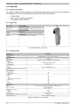
Summary of Contents for X20 System
Page 2: ......


