X20 system modules • Motor controllers • X20MM4456
1966
X20 system User's Manual 3.10
4.25.5.15.3 Configuration
4.25.5.15.3.1 Configuration
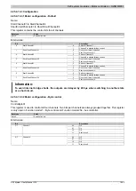
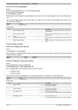
Name:
Configuration01 to Configuration04
These registers can be used to configure the four DC motors.
The following placeholders are used in the configuration table:
Register
[x]
In1
In2
Configuration01
1
DI3
DI4
Configuration02
2
DI7
DI8
Configuration03
3
DI11
DI12
Configuration04
4
DI15
DI16
Data type
Value
UINT
See bit structure.
Bit structure:
Bit
Description
Value
Information
00
ABR counter
[x]
is latched unconditionally (default setting). The
reference enable input is ignored.
01
ABR counter
[x]
is latched if a rising edge occurs on digital input
In1
and the reference enable input
In2
is "1". The reference en-
able input must be activated to do this (see bit 2).
10
ABR counter 1 is latched if a rising edge occurs on digital input
In1
and the reference enable input
In2
is "1". The reference en-
able input must be activated to do this (see bit 2).
0 - 1
Configuration of latch function for ABR counter
[x]
. Activation
of the latch function is described in the control register (bit 2):
11
The latch function is disabled.
0
No reference enable input
2
Reference enable input:
1
Digital input
In2
is used as a reference enable input
0
Active level = High
3
Active level of the reference enable for ABR counter
[x]
:
1
Active level = Low
4 - 5
Reserved
0
00
Limit switch 1 is disabled
01
Digital input
In1
is used as the limit switch
10
Digital input
In2
is used as the limit switch
6 - 7
Definition of the limit switch
[x]
(see also Limit switch function):
11
Digital inputs
In1
and
In2
are used as left and right limit switches
0
Active level = High
8
Active level for limit switch
[x]
:
1
Active level = Low
00
Trigger counter disabled
01
Digital input
In1
is used as trigger input
10
Digital input
In2
is used as trigger input
9 - 10
Trigger input for trigger counter "μs Since Trigger
[x]
":
11
Reserved
0
If the corresponding setting has been activated, then the aver-
age current value is shown in the 4.25.5.15.4.2 "ABR counter"
[x]
register (see bit 5 in the control register)
11
Displays the current average for output
[x]
:
1
If the corresponding setting has been activated, then
the average current value is shown in the 4.25.5.15.4.3
[x]
register (see bit 5 in the control register).
In this case, please refer to the explanations provided under .
0
PWM control
12
Type of control for output
[x]
:
1
Current control
00
Slow decay (default setting)
01
Mixed decay
13 - 14
Decay configuration PWM
[x]
10 - 11
Reserved
15
Reserved
0
Limit switch function
The limit switch function serves to quickly shut off the PWM outputs when a limit position is reached.
The limit switch is activated and the disable edge (rising or falling) on the limit switch input is selected using bits
6 to 8.
A PWM output is deactivated as soon as the configured disable edge is reached on the corresponding input of
the limit switch. It remains deactivated until either the limit switch function is deactivated or the limit switch is
Summary of Contents for X20 System
Page 2: ......


