X20 system modules • Counter modules • X20DC4395
X20 system User's Manual 3.10
881
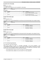
Configure calculation of comparator
Name:
CfO_Counter1event0config to CfO_Counter4event0config (event function 1)
CfO_Counter1event1config to CfO_Counter4event1config (event function 2)
These registers are used to configure the counter event function for the respective counter function.
Bits 0 to 3 configure the calculation of the comparison or to latch the value. This calculation is similar to the calcu-
lation of the counter register (see 4.11.17.12.6.1 "Counter value calculation")
Bits 8 to 13 can be used to limit the number of bits used for the comparison. A mask is calculated as 2
n
- 1 and
linked with an "AND" operation. This makes it possible to generate a comparator pulse every 2
n
increments.
Data type
Value
UINT
See bit structure.
Bit structure:
Bit
Description
Value
Information
0
0 is added instead of "counter 1"
0
counter 1 - use
1
"counter 1" is used for addition
0
The sign of the "counter 1" register is not changed for addition
1
counter 1 - sign
1
The sign of the "counter 1" register is reversed for addition
0
0 is added instead of "counter 2"
2
counter 2 - use
1
"counter 2" is used for addition
0
The sign of the "counter 2" register is not changed for addition
3
counter 1 - sign
1
The sign of the "counter 2" register is reversed for addition
4 - 7
Reserved
-
8 - 13
Number of bits for comparator mask
x
The mask value is calculated as 2
n
-1, where n is value set in
these bits. Default: 0
14
Reserved
-
0
MarginComparator >= (Current position - OriginComparator)
15
Margin comparator mode
1
MarginComparator > (Current position - OriginComparator)
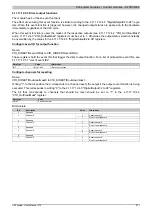
Configure mode and latching of comparator function
Name:
CfO_Counter1event0mode to CfO_Counter4event0mode (event function 1)
CfO_Counter1event1mode to CfO_Counter4event1mode (event function 2)
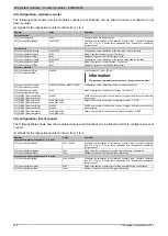
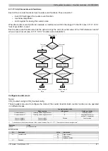
In these registers you can set the mode for the comparator function and optional copying of the latched registers.
Comparator functions can be operated in 4 different modes. For a description, see "Comparator modes".
Bits 4 to 7 can be used to define hardware referencing actions.
Based on these bits, the values of the internal absolute value counters "abs1" and "abs2" can be copied to the re-
spective "HW_reference_counter" register at every counter event (see 4.11.17.12.6.1 "Counter value calculation").
This function can be used to reference the counter values directly in the hardware.
Data type
Value
USINT
See bit structure.
Bit structure:
Bit
Description
Value
Information
0
Off
1
Single
2
State change
0 - 1
Comparator mode
3
Continuous
2 - 3
Reserved
-
0
No action
4
Copy abs1 counter value
1
When event is FALSE → hardware reference counter 1 = abs1
0
No action
5
Copy abs2 counter value
1
When event is FALSE → hardware reference counter 2 = abs2
0
No action
6
Copy abs1 counter value
1
When event is TRUE → hardware reference counter 1 = abs1
0
No action
7
Copy abs2 counter value
1
When event is TRUE → hardware reference counter 2 = abs2
Summary of Contents for X20 System
Page 2: ......


