X20 system modules • Expandable bus controllers • X20BC1083
X20 system User's Manual 3.10
1711
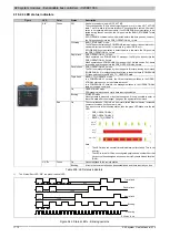
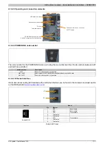
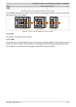
4.19.2.5 Operating and connection elements
LED status indicator
POWERLINK connection with
2 x RJ45 connectors for simple wiring
Node number switches
Terminal block for bus controller
and I/O supply
Slot for
Interface module
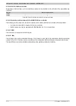
4.19.2.6 POWERLINK node number
The node number for the POWERLINK node is set using the two number switches. Node numbers between 0x01
and 0xEF are permitted.
Switch position
Description
0x00
Reserved, switch position not permitted
0x01 - 0xEF
Node number of the POWERLINK node Operation as a controlled node.
0xF0 - 0xFF
Reserved, switch position not permitted
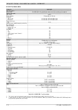
4.19.2.7 Ethernet interface
Information about cabling X20 modules with an Ethernet interface can be found in the module's download section
IF1
IF2
Pinout
Interface
Pin
Ethernet
1
RXD
Receive data
2
RXD\
Receive data\
3
TXD
Transmit data
4
Termination
5
Termination
6
TXD\
Transmit data\
7
Termination
1
Shielded RJ45
8
Termination
Table 499: Pinout
Summary of Contents for X20 System
Page 2: ......


