X20 system modules • Analog input modules • X20AI2437
X20 system User's Manual 3.10
187
4.3.6.9.6 Analog signal - Configuration
How the analog signal is displayed can be adapted to the requirements of the application. Separate configuration
registers per channel are available to aid in this.
4.3.6.9.6.1 Analog mode
Designations (pChannelName):
AnMode_1
AnMode_2
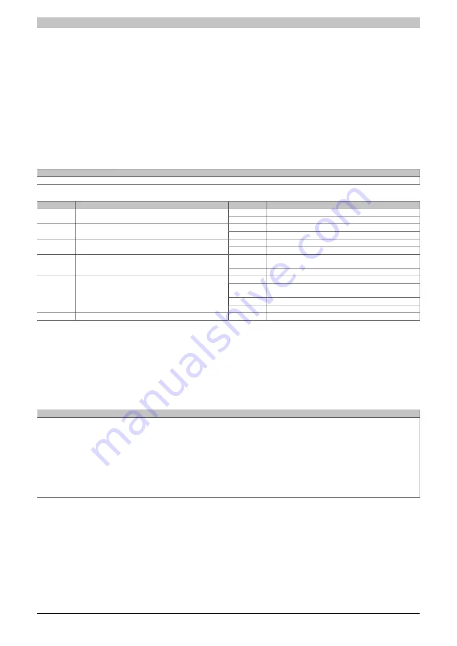
These registers are used to predefine the operating parameters that the module will be using for the respective
channel. Each channel must be enabled individually and can be configured and operated independently.
It is extremely important to not that different limit values need to be configured for any display normalizing that
needs to take place.
Data type
Values
UINT
See bit structure
Bit structure:
Bit
Description
Note
0
Channel 0x turned off
0
Channel
1
Channel 0x enabled (bus controller default setting)
0
Open circuit monitoring turned off
1
Open circuit detection
1
Channel 0x monitoring enabled (bus controller default setting)
0
Underflow detection turned off
2
Underflow detection
1
Underflow detection enabled (bus controller default setting)
0
Use replacement values when an error occurs (bus controller
default setting)
3
Replacement value strategy
1
Keep the last valid converted value
00
Displays 0...25 mA as 0...32767
01
Displays 0...25 mA as 0...25000 [µA] (bus controller default set-
ting)
10
Displays 4...20 mA as 0...32767
4-5
Normalization
11
Displays 0...25 mA as 0...65535
6-15
Reserved
-
4.3.6.9.6.2 Sample rate
Names (pChannelName):
Samplerate_1
Samplerate_2
A sample rate can be configured for both analog inputs independently of one another. The following formula for
this parameter is put together using the desired sampling frequency:
Sample rate for ADC = (4920000/1024)/sampling frequency
Data type
Values
UINT
4 - 1023: Sample rate
960 ... 200 ms
... 5 Hz
480 ... 100 ms
... 10 Hz
320 ... 66.7 ms
... 15 Hz
192 ... 40 ms
... 25 Hz
160 ... 33.3 ms
... 30 Hz
96
... 20 ms
... 50 Hz (bus controller default setting)
80
... 16.7 ms
... 60 Hz
48
... 10 ms
... 100 Hz
9
... 2 ms
... 500 Hz
4
... 1 ms
... 1000 Hz
Setting to 1000 Hz will result in jitter when acquiring measurement values. Jitter-free operation is possible up to
960 Hz (sample rate setting = 5).
Summary of Contents for X20 System
Page 2: ......

