X20 system modules • Module overview: Alphabetically
120
X20 system User's Manual 3.10
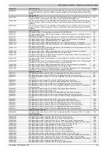
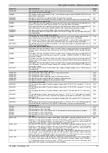
Product ID
Short description
on page
X20 interface module for expandable bus controller, 1 X2X Link master interface, electrically isolated, order 1x
TB704 terminal block separately.
X20 interface module, for DTM configuration, 1 ASi master interface, electrically isolated, order 1x TB704 ter-
minal block separately.
X20 interface module, for DTM configuration, 1 EtherNet/IP scanner (master) interface, electrically isolated
X20 interface module, for DTM configuration, 1 EtherNet/IP adapter (slave) interface, electrically isolated
X20 interface module for DTM configuration, 1 PROFINET RT controller (master) interface, electrically isolated
X20 interface module, for DTM configuration, 1 PROFINET RT device (slave) interface, electrically isolated
X20 interface module for DTM configuration, 1 EtherCAT slave interface, electrically isolated
X20 interface module, 1 redundancy link interface 1000BASE-SX, CPU-CPU data synchronization module for
controller redundancy
X20 interface module, 1x link selector for POWERLINK cable redundancy, POWERLINK functions: - Managing
node - Controlled node for iCN operation - Redundant managing node for CPU redundancy - Ring redundancy
- 2x hub - Multi ASend - PRC function 2x RJ45 connection
X20 interface module, 2 CAN interfaces, max. 1 Mbit/s, electrically isolated, order 2x TB2105 terminal block
separately.
X20 interface module, 1 CAN interface, max. 1 Mbit/s, electrically isolated, 1 X2X Link master interface, elec-
trically isolated, order 1x TB2105 and 1x TB704 terminal block separately.
X20 PWM motor module, 24 to 39 VDC ±25%, 2 PWM motor bridges, 3 A continuous current, 3.5 A peak current,
4 digital inputs 24 VDC, sink, configurable as incremental encoder
X20 digital motor module, 24 VDC, 3 digital outputs, full bridge (H bridge), 3 A continuous current, 5 A peak
current
X20 digital motor module, 24 VDC, 4 digital outputs, half bridge, 3 A continuous current, 5 A peak current
X20 PWM motor module, 24 to 48 VDC ±25%, 4 PWM motor bridges, 6 A continuous current, 10 A peak current,
4x 4 digital inputs 24 VDC, sink, configurable as incremental encoder
X20 potential distributor module, 12x GND, integrated microfuse
X20 potential distributor module, 12x 24 VDC, integrated microfuse
X20 potential distributor module, 5x GND, 5x 24 VDC, floating feed, integrated microfuse
X20 potential distributor module, 6x GND, 6x 24 VDC, with feed option, integrated microfuse
X20 supply module for internal I/O supply
X20 supply module for internal I/O supply, integrated microfuse
X20 supply module for X2X Link and internal I/O supply
X20 supply module for X2X Link and internal I/O supply, integrated microfuse
X20 power supply module for potentiometers, 4x ±10 V for potentiometer supply
X20 supply module for standalone hub and compact link selector
X20 supply module for bus controller and internal I/O supply, X2X Link supply
X20 supply module, for bus controller and internal I/O supply, X2X Link supply, supply not electrically isolated
X20 supply module for compact and fieldbus CPUs and internal I/O supply, X2X Link supply
X20 power supply module for compact and fieldbus and internal I/O supply, X2X Link bus supply, supply not
electrically isolated
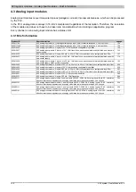
X20 stepper motor module, 1 motor connection, 1 A continuous current, 1.2 A peak current, 4 digital inputs 24
VDC, sink, can be configured as incremental encoder
X20 stepper motor module, module supply 24-39 VDC ±25%, 1 motor connection, 3 A continuous current, 3.5
A peak current, 4 digital inputs 24 VDC, sink, can be configured as incremental encoder
X20 terminal block, 6-pin, 24 V coded
X20 terminal block, 12-pin, 24 V keyed
X20 terminal block, 12-pin, 24 VDC keyed, 2x PT1000 integrated for terminal temperature compensation
X20 terminal block, 16-pin, 24 VDC keyed
X20 terminal block, 12-pin, 240 VAC keyed
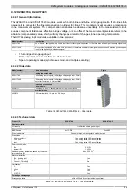
X20 CPU, fieldbus CPU µP 16, 100 kB SRAM, 1 MB FlashPROM, support of RS232, CAN and interface module,
according to fieldbus CPU base, order power supply module, bus base and terminal block separately
X20 CPU, fieldbus CPU µP 25, 750 kB SRAM, 3 MB FlashPROM, support of RS232, CAN and interface module,
according to fieldbus CPU base, order power supply module, bus base and terminal block separately
X20 CPU, fieldbus CPU µP 25, 750 kB SRAM, 3 MB FlashPROM, support of RS232, CAN and interface module,
according to fieldbus CPU base, 1 Ethernet interface 100 Base-T, order bus base, power supply module and
terminal block separately
Dummy X20 module (non-functional)
Dummy X20 module (non-functional)
Summary of Contents for X20 System
Page 2: ......


