X20 system modules • Other functions • X20CM4810
X20 system User's Manual 3.10
2201
4.26.2.6.2 Transferring characteristic values via FlatStream
4.26.2.6.2.1 General information
For information about FlatStream functionality, see section 4.26.2.6.1 "FlatStream communication" on page 2182.
Transferring characteristic values via FlatStream is only available on the module in Function model 0 - Standard
and Function model 2 - Slow master.
Every 300 ms, the characteristic values calculated by the module are transferred automatically via the characteristic
value FlatStream, but only if the previous transfer is already complete. For this reason a maximum X2X Link
cycle time of 10 ms is recommended to prevent measurement data from being lost. It is also important to note
that the module refreshes the data points of the characteristic value FlatStream every X2X Link cycle. Once the
transmission is complete, the characteristic values from the stream need to be "reassembled" on the PLC.
Automation Runtime handles FlatStream communication when transferring characteristic values in the "Standard"
function model. The user is automatically provided with all characteristic values, already properly scaled. Only the
task cycle needs to be checked to make sure it is correct. As a result, the data points for the characteristic value
FlatStream are not shown in the Function model 0 - Standard I/O mapping.
4.26.2.6.2.2 Registers for the characteristic value FlatStream
The following registers are needed to transfer characteristic values:
ParameterInputSequence01
ParameterRxByte01-13
ParameterOutputSequence01
This results in an InputMTU of 13 bytes and an OutputMTU of 0 bytes for the characteristic value FlatStream.
4.26.2.6.2.3 Structure of the characteristic value FlatStream
Each characteristic value transferred from the module via FlatStream has a length of 3 bytes with the high byte
first. For the exact format, see section 4.26.2.2.11 "Characteristic value format" on page 2075. The stream has a
total length of 240 bytes. First, all characteristic values from channel 1 are transferred, then those from channels
2, 3 and 4. The 32 frequency bands then follow next.
The RmsVelRaw and RmsVelEnvelope characteristic values and the frequency bands are only transferred if they
are set to a velocity signal and the EnableVelocityCalculation bit for the respective channel is set. Otherwise, 0 is
output. EnableVelocityCalculation is configured in the "SensorConfig01" register.
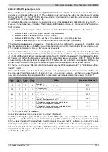
Byte offset in the stream
Channel 1
Channel 2
Channel 3
Channel 4
Characteristic value
Channel parameters
0
36
72
108
3
39
75
111
6
42
78
114
9
45
81
117
12
48
84
120
15
51
87
123
18
54
90
126
21
57
93
129
24
60
96
132
27
63
99
135
30
66
102
138
33
69
105
141
Frequency band 1 - 32
144
FrequencyBand01
:
:
237
FrequencyBand32
Summary of Contents for X20 System
Page 2: ......


