X20 system modules • Counter modules • X20DC2190
786
X20 system User's Manual 3.10
4.11.13.7.3 Commissioning a transducer rod
Two registers need to be configured to initialize an ultrasonic transducer rod and receive valid measurements. The
first step is to enter the length of the rod (see section 4.11.13.7.12 "Rod length 1 and 2" on page 789). The wave
propagation speed for the rod must then be defined (see section 4.11.13.7.8 "Ultrasonic speed specification" on
page 787). This information can usually be found directly on the transducer rod itself or in its data sheet.
If the plausibility limits remain set to 0 (default value), one of the respective ErrorStatus registers will now indicate
faulty readings or plausibility errors. If this is the case, plausibility mode can be disabled using the "ConfigOutput01"
register (see section 4.11.13.7.10 "Module configuration" on page 788). This will cause the positions of the mag-
nets to be displayed on the rod.
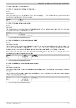
4.11.13.7.4 Reading the magnet position
Name:
Position01 - Position04
These registers contain the position of the individual magnets on the transducer rods.
Data type
Value
DINT
-2,147,483,648 to 2,147,483,647: Resolution 1 µm
4.11.13.7.5 Reading the magnet speed
Name:
Speed01 to Speed04
These registers contain the speed of the individual magnets on the transducer rods. A resolution of 0.1 mm/s is
achieved by calculating the speed from 2 position values within a 100 ms interval.
Data type
Value
INT
-32768 to 32767: Resolution 0.1 mm/s
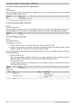
4.11.13.7.6 Error status
Name:
ErrorStatus01 to ErrorStatus04
These registers can be used to indicate the error status for individual channels.
Data type
Value
USINT
See bit structure.
Bit structure
Bit
Description
0 - 3
Counter for plausibility errors (cyclic)
4 - 7
Counter for mis-measurements (cyclic)
Possible reasons for plausibility errors:
•
Configured max. or min. path of a magnet was exceeded
•
Configured max. speed was exceeded
Possible reasons for faulty measurements:
•
Configured rod length was exceeded
•
Rod failure
•
Missing measurement magnet
Information:
If the registers "USSpeed01" and "USSpeed02" are unequal to 0 after the module starts up, the respec-
tive error counters on slower fieldbus systems (e.g. CAN I/O) may continue to count until the module
configuration is completed. In some cases, this is due problems between the respective rod and the
default configuration.
Summary of Contents for X20 System
Page 2: ......

