


Drive control and features
62
Because the drive speed control uses motor speed, a gear function between position
control (load side) and speed control (motor side) is needed. This gear function is
formed from the motor gear function and inverted load gear function. The gear
function is applied to the position control output (speed reference) as follows:
The equation quite often translates to
Parameters
are also inputs
of the firmware block
(see page
Note:
It is emphasised that all position relevant parameters are load side related, eg,
the setting of parameter
(dynamic limiter speed limitation) of
300 rpm denotes that, with a load gear ratio of 1:10, the motor can run at up to 3000
rpm.
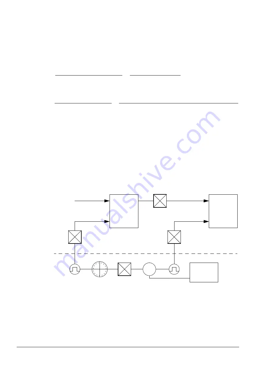
Examples of gear function usage
The following figures demonstrate how the gear functions of the control program are
used.
=
Motor speed
Load speed
=
Drive firmware
Position
control
Position ref.
Speed
control
Gear ratio
Speed ref.
Speed act.
n1:n2
Position act.
1:1
Load encoder gear
/
1:1
Motor encoder gear
n2:n1
M
Mechanical set-up
Drive
hardware
Summary of Contents for ACSM1 Series
Page 1: ...ABB motion control drives Firmware manual ACSM1 motion control program ...
Page 4: ......
Page 34: ...Drive programming using PC tools 34 ...
Page 86: ...Drive control and features 86 ...
Page 265: ...Parameters and firmware blocks 265 1 100 us 100 µs 2 1 ms 1 ms 3 50 ms 50 ms ...
Page 302: ...Parameter data 302 ...
Page 422: ...Application program template 422 ...
Page 430: ...Appendix A Fieldbus control 430 ...
Page 500: ...Appendix D Application examples 500 ...
Page 508: ...Appendix E Control chain and drive logic diagrams 508 ...
Page 510: ...3AFE68848270 REV H EN 2015 06 26 Contact us www abb com drives www abb com drivespartners ...


